


34
Image Projection (Continued)
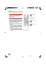
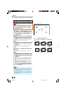
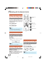
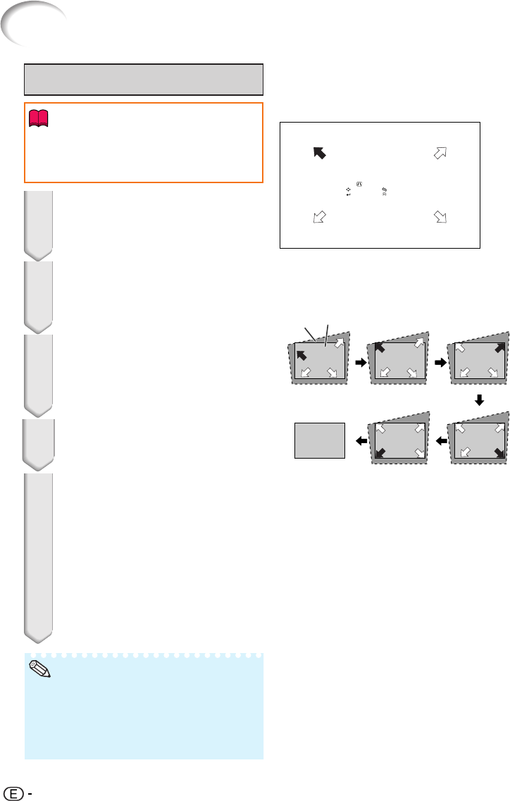
ROn-screen display
GEOMETRIC ADJUSTMENT
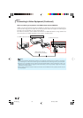
Geometric Adjustment
Adjust upper left corner
GEOMETRIC ADJUSTMENT
ADJUST
NEXT
RESET
END
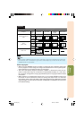
Blue
area
Screen
Upper Left Upper Right
Lower Left Lower Right
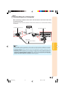
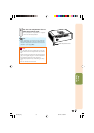
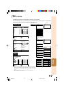
2
Press c KEYSTONE on the re-
mote control repeatedly until
“GEOMETRIC ADJUSTMENT” is
displayed.
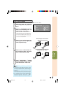
3
Press P, R, O or Q to move the
position for the upper left of the
image.
• Adjust the screen until the displayed red
arrows line up in the upper left.
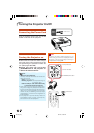
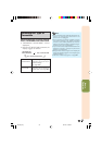
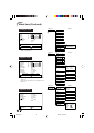
4
Press i ENTER to set the posi-
tion.
• The arrow in the upper right turns red.
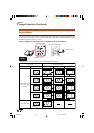
5
Repeat the same procedure with
the positions for the upper right,
lower right and lower left of the
image.
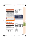
• When you press e RETURN at this point,
you will return to the previous screen.
• If you press e RETURN before adjust-
ing the upper left corner, the Reset Con-
firmation screen displays.
• When you confirm the lower left posi-
tion, the screen adjustments will be set
and the “GEOMETRIC ADJUSTMENT”
mode will end.
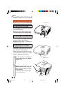
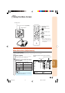
1
Adjust the focus, size, and projec-
tion angle so that the screen
edges line up into the blue area.
• Line up the screen edges into the blue
area as closely as possible.
• The placement of the screen and the projector
may result in the image aspect ratio becoming
slightly distorted.
• Try “H&V KEYSTONE” when “GEOMETRIC
ADJUSTMENT” does not fully correct trapezoi-
dal distortion.
Note
• When adjusting a 4:3-aspect-ratio input sig-
nal to a 4:3-aspect-ratio screen, correct the
trapezoidal distortion by setting “RESIZE”
to “STRETCH” (16:9).
Info
DT-500_EN_h 06.2.16, 10:00 AM34