


46
33
33
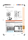
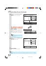
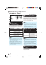
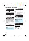
3 Auto Sync (Auto Sync
Adjustment)
• Auto Sync adjustment is also performed by
pressing f AUTO SYNC on the remote con-
trol.
• The Auto Sync adjustment may take some time
to complete, depending on the image of the
computer connected to the projector.
• When the optimum image cannot be achieved
with Auto Sync adjustment, use manual ad-
justments.
Note
Selectable items
On
Off
Description
Auto Sync adjustment will
occur when the projector is
turned on or when the input
signals are switched, when
connected to a computer.
Auto Sync adjustment is not
automatically performed.
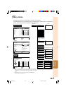
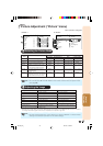
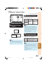
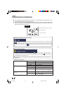
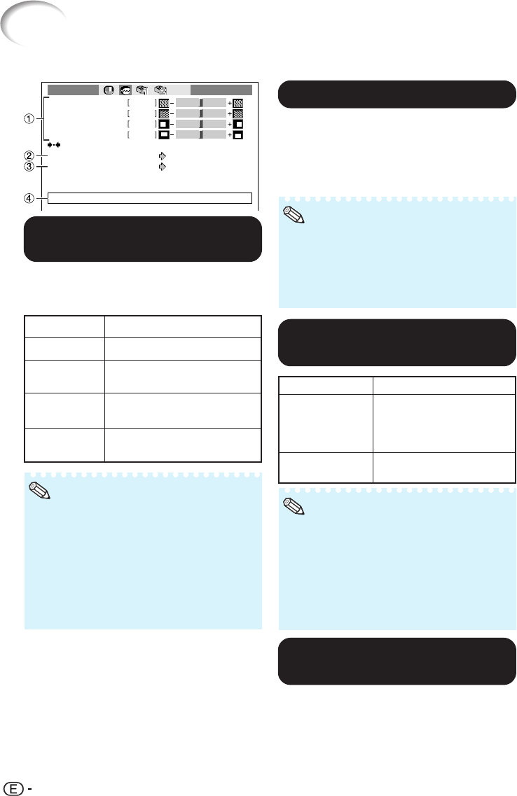
Computer Image Adjustment
(“Fine Sync” menu)
Clock
Phase
0
0
0
0
H-Pos
V-Pos
Special Modes
Cur. sig. freq : H 33.8 kHz / V 60 Hz
Auto Sync
On
1080I
Fine Sync INPUT 5
Reset
Menu operation n Page 41
11
11
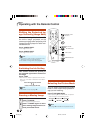
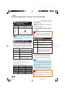
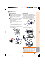
1 Adjusting the
Computer Image
Use the Fine Sync function in case of irregulari-
ties such as vertical stripes or flickering in por-
tions of the screen.
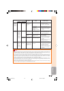
Selectable items
Clock
Phase
H-Pos
V-Pos
Description
Adjusts vertical noise.
Adjusts horizontal noise (similar
to tracking on your VCR).
Centers the on-screen image by
moving it to the left or right.
Centers the on-screen image by
moving it up or down.
• You can automatically adjust the computer
image by setting “Auto Sync” in the “Fine
Sync” menu to “On” or pressing f AUTO
SYNC on the remote control.
• “Clock”, “Phase”, “H-Pos” and “V-Pos” can-
not be adjusted when INPUT 6 is selected.
• The adjustable area of each item may be
changed according to the input signal.
• To reset all adjustment items, select “Reset”
and press i ENTER.
Note
22
22
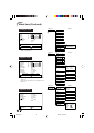
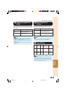
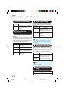
2 Special Modes Setting
Ordinarily, the type of input signal is detected
and the correct resolution mode is automatically
selected. However, for some signals, the opti-
mal resolution mode in “Special Modes” in the
“Fine Sync” menu may need to be selected to
match the computer display mode.
• Avoid displaying computer patterns which
repeat every other line (horizontal stripes).
(Flickering may occur, making the image hard
to see.)
• Information on the currently selected input sig-
nal can be confirmed in item 4.
Note
44
44
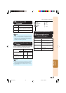
4 Checking the Input
Signal
This function allows you to check the current in-
put signal information.
DT-500_EN_j 06.2.16, 10:02 AM46