


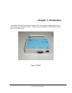
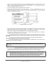

PHYSICAL PORTS
The physical ports on the SX-500 are as follows:
Port Name Description
Power Jack for attachment of external power supply
Ethernet RJ-45 connector for attachment of Ethernet cable
Serial DB-9 connector for attachment of serial interface cable
Wireless RP-SMA connector for attachment of an external antenna
Button Momentary push button
LED Green, Yellow and Orange LEDs
For installation and connection of the interface ports, refer to Chapter 2.
Logical Ports
The SX-500 has logical interfaces for transfer of data and for configuration and control of the unit.
These logical interfaces may share a physical port. The application firmware in the SX-500
separates and routes the data to the appropriate internal firmware task associated with the logical
interface. For network ports (Ethernet, Wireless) this separation is based on the TCP or UDP
protocol port number. For the serial port, data or control/status mode is controlled by specific
protocol strings, only one mode is active at a time. Serial port control/status mode is only
available if the unit is explicitly configured to allow it. The following table describes the logical
interfaces of the unit when operating in a FIPS 140-2 approved mode.
FIPS-140-2 Interface Physical
Interface
Logical Interface
Data Input Serial Plaintext data for transmission to network
Ethernet Plaintext data for bridging to wireless
network
Wireless Ciphertext data for Serial or Ethernet port
Data Output Serial Plaintext data received from wireless
network
Ethernet Plaintext data received from wireless
network
Wireless Ciphertext data from Serial or Ethernet port
Control Input Ethernet Control data for console task received via
Telnet
Control data for web config task received
via HTTP
Wireless Control data for console task received via
Telnet
Control data for web config task received
via HTTP
Introduction Silex Page 4
Part Number 140-00188-210A