28 Zeus
IOPS
3.5-Inch Fibre Channel Solid State Drive Product Manual Rev. 1.0
ELECTRICAL SPECIFICATIONS
POWER SUPPLY
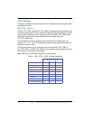
The following voltage specification applies to the drive power connector. Connections to the drive
should be made in a safety extra low voltage (SELV) circuit.
The drive does not use the +5V supply input pins available on a typical 40-Pin SCA-2 connector.
The drive uses the +12V supply input. The 5V ground pins are connected to the common ground
plane within the unit.
Adequate secondary over-current protection must be incorporated in the host system (drive
enclosure, backplane, etc.). A 10 amp limit is required for safety purposes.
POWER REQUIREMENTS
The Zeus
IOPS
3.5-inch Fibre Channel SSD requires a 12V +/-10% DC power source. If a power
failure occurs, the drive design ensures that the data contained in the storage memory is preserved.
Data loss or corruption does not occur.
Table 5. Zeus
IOPS
3.5-Inch SSD Power Requirements
POWER CONSUMPTION
Table 6. Zeus
IOPS
Fibre Channel SSD Typical Power Consumption
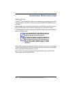
CAUTION: To avoid damage to the drive, power
supply voltage transients must not exceed 16
volts.
Item Requirement
Input Voltage 12V +/-10%
Minimum Voltage 10.8
Maximum Voltage 13.2
Activity Average Current (mA) Average Power (W)
Startup 1,200 14.4
Idle 450 5.4
Max Read @ 200MB/sec 700 8.4
Max Write @ 100MB/sec 675 8.1
Read, 1 Block Random I/O @ > 50,000 525 6.3
Write, 1 Block Random I/O @ > 18,000 660 7.9


