


Zeus
IOPS
3.5-Inch Fibre Channel Solid State Drive Product Manual Rev. 1.0 31
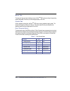
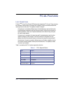
P_ESI_n FUNCTION
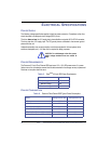
The SEL_N (TTL compatible) inputs and outputs (defined when -Parallel ESI is asserted) provide an
interface between the enclosure and the drive. Table 8 summarizes the signals.
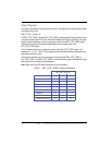
Table 8. SEL_N/P_ESI_N Signal Definitions
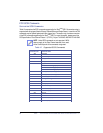
SFF-8045 ENCLOSURE SERVICE INTERFACE
The SFF-8045 Enclosure Service Interface defines 7 bits of enclosure status. This status is read by
the drive, and presented to the Initiator, upon receipt of appropriate Receive Diagnostic command.
The definitions of the status bits are vendor specific. The drive will not interpret the status. The drive
assumes -EFW is status and treats it as if does the other P_ESI_n signals.
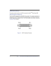
-ENBL_BYP CH1 AND -ENBL_BYP_CH2
These two signals are TTL outputs from the drive and provide 4mA of sink capability. The signals are
intended to control the state of the loop port bypass circuit on the backplane. The drive powers up
with these signals turned off. It is assumed that the backplane will provide a 1K ohm pull-down
resistor that will ensure the drive is bypassed on the loop when it is not present, or when it is powering
up. The drive will attempt to enable itself on both loops after a successful power up.
START_n MATED
These signals are used to control the motor spin on rotating media drives. Because the Zeus
IOPS
SSD is a solid-state device and has no motor, these signals are ignored by the drive.
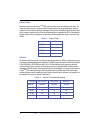
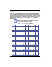
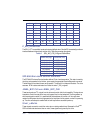
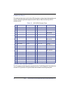
17 C5 37 81 57 4C 77 17
18 C3 38 80 58 4B 78 10
19 BC 39 7C 59 4A 79 F
1A BA 3A 7A 5A 49 7A 8
1B B9 3B 79 5B 47 7B 4
1C B6 3C 76 5C 46 7C 2
1D B5 3D 75 5D 45 7D 1
1E B4 3E 74 5E 43 7E NA
1F B3 3F 73 5F 3C 7F SOFT
-Parallel ESI (High) -Parallel ESI (Low)
Sel_0 (Input) P_ESI_0 (Input)
Sel_1 (Input) P_ESI_1 (Input)
Sel_2 (Input) P_ESI_2 (Input)
Sel_3 (Input) P_ESI_3 (Input)
Sel_4 (Input) P_ESI_4 (Input)
Sel_5 (Input) P_ESI_5 (Input)
Sel_6 (Input) -EFW (Input)