


C
ABLES
B-2
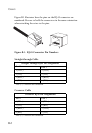
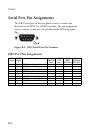
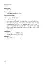
Figure B-1 illustrates how the pins on the RJ-45 connector are
numbered. Be sure to hold the connectors in the same orientation
when attaching the wires to the pins.
Figure B-1. RJ-45 Connector Pin Numbers
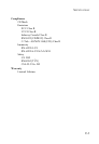
Straight-through Cable
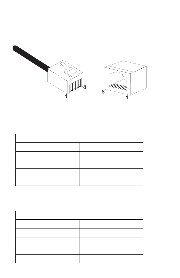
Crossover Cable
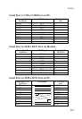
Straight-Through RJ-45 Pin Assignments
End 1
End 2
1 (TD+) 1 (TD+)
2 (TD-) 2 (TD-)
3 (RD+) 3 (RD+)
6 (RD-) 6 (RD-)
Pins 4, 5, 7 and 8 are not connected.
Crossover RJ-45 Pin Assignments
End 1
End 2
1 (TD+) 3 (RD+)
2 (TD-) 6 (RD-)
3 (RD+) 1 (TD+)
6 (RD-) 2 (TD-)
Pins 4, 5, 7 and 8 are not connected.