


5-52
ROUTING SWITCHER SYSTEM (E)
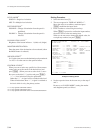
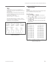
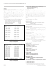
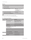
5-4. Setting Items of the Secondary Station on Monitor S-BUS (BKDS-V3293B only)
MONITOR SYSTEM SETUP MENU BKS-R3210 V1.10 STATION NUMBER 6
SOURCE
name Description name Description
1 IN001 CAM001 2 IN002 CAM002
3 IN003 CAM003 4 IN004 CAM004
5 IN005 VTR005 6 IN006 VTR006
7 IN007 VTR007 8 IN008 VTR008
9 IN009 ONAIR01 10 IN010 ONAIR02
11 IN011 ONAIR03 12 IN012 ONAIR04
13 IN013 STADIO1 14 IN014 STADIO2
15 IN015 STADIO3 16 IN016 STADIO4
17 IN017 MONI001 18 IN018 MONI002
19 IN019 IN019 20 IN020 IN020
21 IN021 IN021 22 IN022 IN022
23 IN023 IN023 24 IN024 IN024
25 IN025 IN025 26 IN026 IN026
27 IN027 IN027 28 IN028 IN028
29 IN029 IN029 30 IN030 IN030
31 IN031 IN031 32 IN032 IN032
Ctrl-E:MENU Ctrl-D:RETURN Right:DESTINATION Left:SOURCE
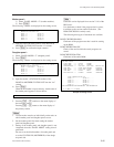
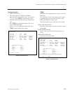
MONITOR SYSTEM SETUP MENU BKS-R3210 V1.10 STATION NUMBER 6
DESTINATION
name Description name Description
1 OUT001 DST001 2 OUT002 DST002
3 OUT003 DST003 4 OUT004 DST004
5 OUT005 DST005 6 OUT006 DST006
7 OUT007 DST007 8 OUT008 DST008
9 OUT009 OUT009 10 OUT010 OUT010
11 OUT011 OUT011 12 OUT012 OUT012
13 OUT013 OUT013 14 OUT014 OUT014
15 OUT015 OUT015 16 OUT016 OUT016
17 OUT017 OUT017 18 OUT018 OUT018
19 OUT019 OUT019 20 OUT020 OUT020
21 OUT021 OUT021 22 OUT022 OUT022
23 OUT023 OUT023 24 OUT024 OUT024
25 OUT025 OUT025 26 OUT026 OUT026
27 OUT027 OUT027 28 OUT028 OUT028
29 OUT029 OUT029 30 OUT030 OUT030
31 OUT031 OUT031 32 OUT032 OUT032
Ctrl-E:MENU Ctrl-D:RETURN Right:DESTINATION Left:SOURCE
*1:Applicable to BKS-R3210 only.
*2:Applicable to BKS-R1607 only.
*3:When monitor S-BUS is used, select STAND ALONE= Stand alone
machine at all times since mother-daughter setting is not necessary.
n
In BKS-R1607/R1608/R3209/R3210 of version V1.10 and
higher, the 160 description names that are transferred from
the primary station can be registered in the range of inputs
512 x outputs 512 in the order of terminal number regard-
less of the block number. When you want to use more than
160 of the description names, transmit the names from the
primary station after dividing the description names into
several blocks.
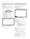
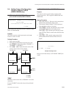
The following operations are possible from the screen.
Look at destination from source side : [*] key
Look at source from destination side : [&] key
Return to the previous page : [(] key
Move to the next page : [)] key
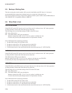
Example of Setting Screen
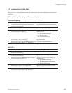
Example of Setting Screen
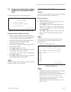
Z : SET PANEL STATUS (BKS-R1607/R1608/
R3204/R3205/R3209/R3210)
<MONITOR MENU>
Purpose
Set the various modes of the remote control unit.
Number of sources and destinations that can be controlled
from the remote control unit, can be expanded by connect-
ing multiple mother and daughter panels. Setting the
mother and daughter panels are also performed using this
menu. (Ten mother panels can be registered at the maxi-
mum.)
The setting contents are as follows.
DISPLAY MODE
STATUS= Displays the status of the primary station
crosspoint table.
PROMPT= The pressed buttons lit immediately.
PROTECT MODE
ON AIR= Execute switching from the panel even during
the protect mode.
NORMAL= Switching is not possible during the protect
mode.
PHANTOM PROTECT
PART PROT= Execute switching on the phantom on
which protect is not set.
FULL PROT=Switching is not executed on all phantoms
when any of the phantom is set to PRO-
TECT ON.
BUTTON LINK=Switching is not executed on all
phantoms when the PROTECT button
on the panel is set to ON.
PANEL MODE
*3
STAND ALONE= Stand alone panel
MOTHER= Mother panel
DAUGHTER= Daughter panel
PANEL LAYOUT
*1
TYPE + NUM.= Selecting X-Y
DIRECT= Selecting direct
LEVEL MODE
*1
SINGLE= Selecting a single level
MULTI= Selecting multiple levels
DEST SELECTION
*2
DISABLE=The destination change from panel is
disabled.
ENABLE=The destination change from panel is enabled.