


4-14
ROUTING SWITCHER SYSTEM (E)
4-4. Basic Setup Procedures
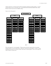
Now select suitable names for sources/destinations using Type name, and number and enter them in the
IN/OUT list of each routing switcher (menu item [C]).
Remember that you have to attention to the ins, and outs of routing switchers on all levels when you build
this list.
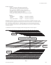
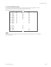
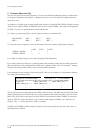
Example :
VIDEO ROUTER SOURCE
Connected to Connector Source Name
CAMERA-1 17 017=CAM001
CAMERA-2 18 018=CAM002
VTR-1 1 001=VTR001
VTR-2 2 002=VTR002
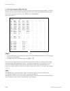
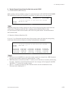
VIDEO ROUTER DESTINATION
Connected to Connector Destination Name
VTR-1 1 001=VTR001
VTR-2 2 002=VTR002
VTR-3 3 003=VTR003
VTR-4 4 004=VTR004
n
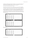
After destination (crosspoint/output) names have been set, the Protect mode may be implemented for that
destination (crosspoint can’t select another input).
After source (inputs) names have been set, the Secret mode may be implemented for the source (input not
selectable by control panels).
Both of these modes can be only be set, or disabled via the terminal.