


5-25
ROUTING SWITCHER SYSTEM (E)
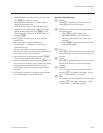
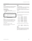
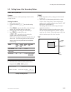
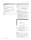
5-2. Setting Items of the Secondary Station
(Input)
512
1
1
164 101
101
164
512
(Output)
Setting
Area
DVS-V6464B
Location
5-2. Setting Items of the Secondary Station
A:SET UNIT LOCATION
Purpose
This menu is used to set the input/output location of the
routing switcher.
Setting Procedure
1. Select menu item [A].
2. Use the cursor keys ([&], [*] to select the setting
item.
3. When [Enter] is pressed, the offset value of the input
number and the output number can be typed.
4. Enter the offset value using the numerical keys.
5. Press [Enter] to set the offset value.
If [Ctrl] _ [F] is pressed before the setting, the
original offset value will be returned.
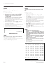
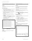
The location is assigned consecutive numbers from the
offset value. The following table lists the input and
output control area assigned from the head number
consecutively.
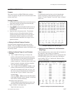
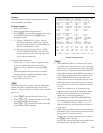
Model Input Output Setting Equivalent
Control Control area Unit
area area
DVS-V6464B 64 64 1 to 512
DVS-V3232B 32 32 1 to 512
HDS-V3232
BVS-A3232 256 32 1 to 256 DVS-TC3232
BVS-V3232
BVS-A3232
DVS-V1616 16 16 1 to 512
DVS-RS1616 128 16 1 to 128
6. The menu screen of the secondary station will be
displayed when [Ctrl] _ [E] is pressed.
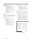
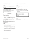
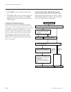
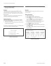
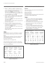
Example of Setting Screen
m
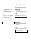
1. In the initial status (factory setting), the head number
is set to “1”.
2. When DVS-V3232B/V6464B, BKPF-R70 or HDS-
V3232 is used as the primary station, input/output
number can be set freely using the menu item [L : SET
PHYSICAL ASSIGNMENT].
The setting values in this menu are physical input/
output/level numbers.
When selecting crosspoints from the remote control
unit, the virtual input/output/level numbers set at the
menu item [L] are used. In the initial status of [L], the
physical numbers equal the virtual numbers.
SET UNIT LOCATION DVS-V6464B V2.10 STATION NUMBER 1
SOURCE No 0001-0064 DESTINATION No 0001-0064 LEVEL No 1
Ctrl-E:RETURN TO MENU