


4-12
ROUTING SWITCHER SYSTEM (E)
4-4. Basic Setup Procedures
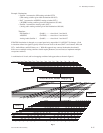
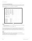
With this approach sources, and destinations like the VTR’s would be level mapped together so that all 3
routing switchers switch at the same time under the VTR001, VTR002, etc. label.
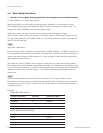
But in the case of output 11, of each of the 3 routing switchers, the 1, and 3 levels (SDI, and analog audio
respectively) would be level mapped and switched together (REM001) while output 11 of level 2, which
is DAT003 would be virtually mapped off away from the other 2, so that it could be easily switched on
it’s own.
Example : Level 1, & level 3 outputs 11 are tied together under the REM001 label
Level 2, mapped out from under level 1 output 11 under the DAT003 label
If DAT003 destination is changed on a control panel only level 2 output 11 crosspoint on the AES/EBU
routing switcher changes. If REM001 destination is changed both levels 1, and 3 change. This approach
is good for a mixture of signals where routing levels follow in some instances, but not always.
n
Sources/Destinations where all associated crosspoints on all levels should follow would be mapped only
by levels. Sources/Destinations which shouldn’t follow would be mapped virtually.
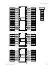
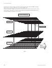
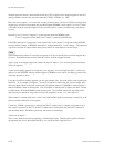
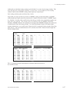
Again, a pure level mapping approach is where all physical inputs 1, 2, etc are tied together on different
levels (see figure 4).
A pure level mapping approach is usually the worst approach. In our example here DAT 3, which is on
output 11 of the AES/EBU routing switcher appears as REM001 on all control, and display, panels if the
level only approach is taken.
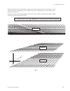
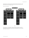
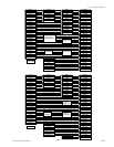
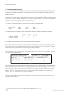
Using the virtual/level mixture approach you will get separate video, and audio tallies (control panel push
button lit). As an example, (see figures 7, and 8) if you use the 2 entries from the virtual example above
and assign both of them to the same control panel (on different buttons), if REM001 is selected with it’s
button, the REM 1 button is tallied green. Now if DAT001 is selected with it’s button, the DAT 3 button
is tallied amber, while the REM001 button remains green. The DAT001 button will stay tallied when
other sources are selected as long as those sources are assigned to level 1, or 3, and not level 2.
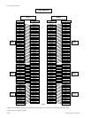
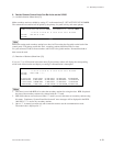
When a button is selected with levels 1, and 2 active the DAT001 audio source button is turned off, as the
primary switches both levels of crosspoints.
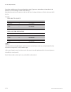
Conversely, if REM 1 (green tally) is selected, and DAT 3 (amber tally) is selected, and another level 2
only source is selected, say DAT 2, the DAT 3 amber tally will extinguish, and the DAT 2 button will
now be tallied amber. The REM 1 green tally will remain on, unchanged.
A final note on figure 7.
This is a two dimensional drawing depicting a 3 dimensional object. Therefore the top half of the draw-
ing represents the X axis, the bottom half the Y axis, and from left to right the Z axis.