


4-18
ROUTING SWITCHER SYSTEM (E)
4-4. Basic Setup Procedures
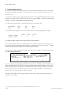
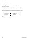
SONY ROUTING SYSTEM SETUP MENU
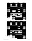
SET PHANTOM TABLE(PHANTOM:DESTINATION<SOURCE-LEVEL)(G.PAHNTOM NAME:NUMBER)
SAT999:0001 CAM999:CAM001<STU111 -1 CAM999:CAM002<STU111 -1
CAM999:CAM003<STU111 -1 CAM999:CAM004<STU111 -1 ......:......<...... -.
......:......<...... -. ......:......<...... -. ......:......<...... -.
......:......<...... -. ......:......<...... -. ......:......<...... -.
BKS-R3206 V3.11 STATION NUMBER 4
*1 : Up to 64 crosspoint changes can be stored in BKS-R1607/R1608/R3209/R3210 of Ver. 1.10.
5. Phantoms (Menu Item [H])
Now we will create any necessary phantoms. First we must define the phantom globally, and then allow
it’s usage by individual control panels. A phantom allows you to have a number of outputs select new
inputs all at once.
An instance of a global in our example would be the selection of input SAT001 (SDI level and the Analog
audio level) to output VTR001, and DIG201 (AES level) to output VTR001. We could call this phantom
SAT999. It’s entry as a global phantom would look like this
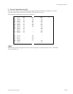
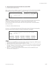
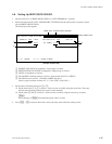
(1) In the top of menu item [H] we would assign our name to a numbered label:
0001 SAT999 0002 ...... 0003 ...... 0004 ......
0005 ...... 0006 ...... 0007 ...... 0007 ......
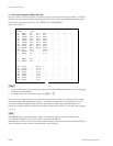
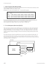
(2) Once the name is assigned we are in an edit menu, where we actually assign inputs to outputs:
1=SDI 2=AES 3=AUD
VTR001 < SAT001 1 .... 3
VTR001 < DIG201 .... 2 ....
Up to 4096 crosspoint changes can be stored among the Global phantoms.
For a control panel to be able to use a global phantom, that secondary station must be called (menu item
[R]), and the name of the global phantom loaded into it’s phantom table. Up to 57 crosspoint
*1
changes
can be stored among each secondary stations (control panels) phantoms.
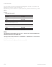
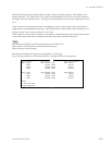
Local phantoms may be created in each control panel. Below is an example of a local phantom residing
in a control panels phantom table :
We can see here that our global phantom SAT999 is the first entree. The 0001 that trails SAT999 means
that this global phantom is the first entry in our global phantom table (menu item [H]). Next we can see
that locally (only at this control panel) we have defined a local phantom called CAM999. It selects the
Studio A (STU111) input, and sends it to our 4 camera return outputs (CAM001, etc.) whenever it is
selected. The “_1” means that level 1 (SDI) is switched.
SAT999, and CAM999 could be assigned to buttons on this control panel just like any other source, or
destination name could be.