


1-6
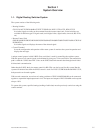
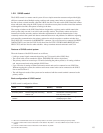
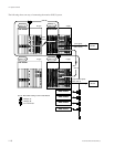
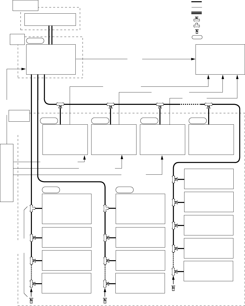
ROUTING SWITCHER SYSTEM (E)
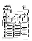
Either one of the REMOTE 1 connectors of the secondary station routing switchers can be used.
*1: The function switch will be not working in the terminal mode of the Windows 95/NT.
*2: (M) and (S) mean the setting of M/S switch on the CPU board.
*3: Connect the 75 Z terminators to the T type bridge of the last device on a S-BUS data link and to the unused REMOTE 1 connector.
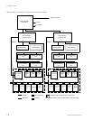
1-2. System Control
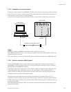
Control
Terminal
<Video>
<Video>
REMOTE 1
REMOTE 1
REMOTE 1
Personal computer with a
communication software or
Windows 3.1 installed
*1
Video Routing Switcher
DVS-V64646B
(M)
*2
Destination VTR
Primary
Station
Level 1
REMOTE 3
Audio Routing Switcher
DVS-A3232
(S)
*2
Audio Routing Switcher
DVS-A3232
(S)
*2
Video Routing Switcher
DVS-V6464B
(S)
*2
Remote Control Unit
BKS-R3210
Source
VTR
Level 3
Time Code
Routing Switcher
DVS-TC3232
(S)
*2
Level 4
Level 2
Level 1
Level 8
<Audio Channel 1/2>
<Audio Channel 3/4>
<Time Code>
<Time Code>
<Audio Channel 1/2>
: S-BUS
: Signal Line
: RS-232C
: T Bridge (A)
: T Bridge (B)
: 75 ZTerminator
*3
: Matrix Level
Remote Control Unit
BKS-R3209
Remote Control Unit
BKS-R3209
Video Routing Switcher
DVS-V3232B
(S)
*2
Remote Control Unit
BKS-R1607
Level 1
Remote Control Unit
BKS-R3209
Remote Control Unit
BKS-R3209
Display Unit
BKS-R3281
Display Unit
BKS-R3280
Remote Control Unit
BKS-R3209
Remote Control Unit
BKS-R1608
Remote Control Unit
BKS-R3209
<Audio channel 3/4>
Routing Switcher
(S)
*2
Secondary
Station
Maximum
253 units
Maximum
128 unit
Example of S-BUS control system connection