


6.Command Specification READ BUFFER
6-72 SONY AIT-3Ex drive SDX-800V series Ver.1.1
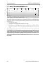
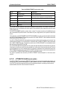
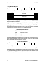
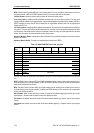
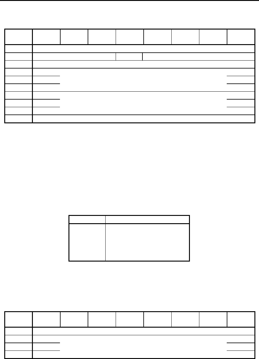
6.15. READ BUFFER 3Ch
Bit
Bite
7 6 5 4 3 2 1 0
0 Operation Code (3Ch)
1 Obsolete Reserved Mode
2 Buffer ID
3 (MSB)
4 Buffer Offset
5 (LSB)
6 (MSB)
7 Allocation Length
8 (LSB)
9 Control
READ BUFFER is used in conjunction with WRITE BUFFER as a diagnostic function for testing the data buffer and
the SCSI bus integrity of the drive. A REWIND command should be sent to the drive after WRITE/READ BUFFER
diagnostic testing to return to normal operation.
Note: This command may not be used to recover data that is buffered within the drive. If the drive receives a READ
BUFFER without having had a prior WRITE BUFFER command, only the four byte header will be returned. There is
no available data to return, as the drive writes any buffered data to tape prior to accepting either a READ BUFFER or
WRITE BUFFER for the first time.
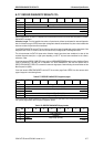
Mode: The drive supports the following values within this field. If any other value is set, the drive will terminate the
command with a CHECK CONDITION status and an ILLEGAL REQUEST sense key set.
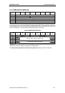
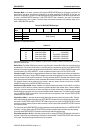
Table 6-70: READ BUFFER Mode values
Mode Description
0000b
0010b
0011b
1010b
1011b
Combined Header and Data
Data
Descriptor
Echo Buffer
Echo Buffer Descriptor
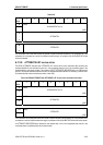
Combined Header and Data Mode-in this mode, the drive returns a four-byte header followed by the data bytes. The
drive terminates the DATA IN phase when Allocation Length bytes of header plus data have been transferred or
when the header and all available data have been transferred to the initiator, whichever is less. The four-byte READ
BUFFER header is followed by data bytes from the drive's data buffer.
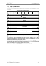
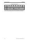
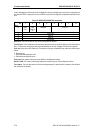
Table 6-71: READ BUFFER Header
Bit
Byte
7 6 5 4 3 2 1 0
0 Reserved
1 (MSB)
2 Available Length
3 (LSB)
Available Length: specifies the total number of data bytes that are available in the target's data buffer. This number
is not reduced to reflect the Allocation Length nor is it reduced to reflect the actual number of bytes written using the
WRITE BUFFER command. Following the READ BUFFER header, the target will transfer data from its data buffer.
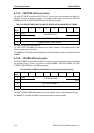
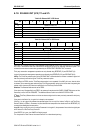
Data Mode - in this mode, the DATA IN phase contains buffer data only.