


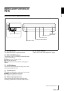
NSP 100
Overview
Names and Functions of Parts
6
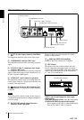
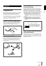
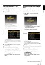
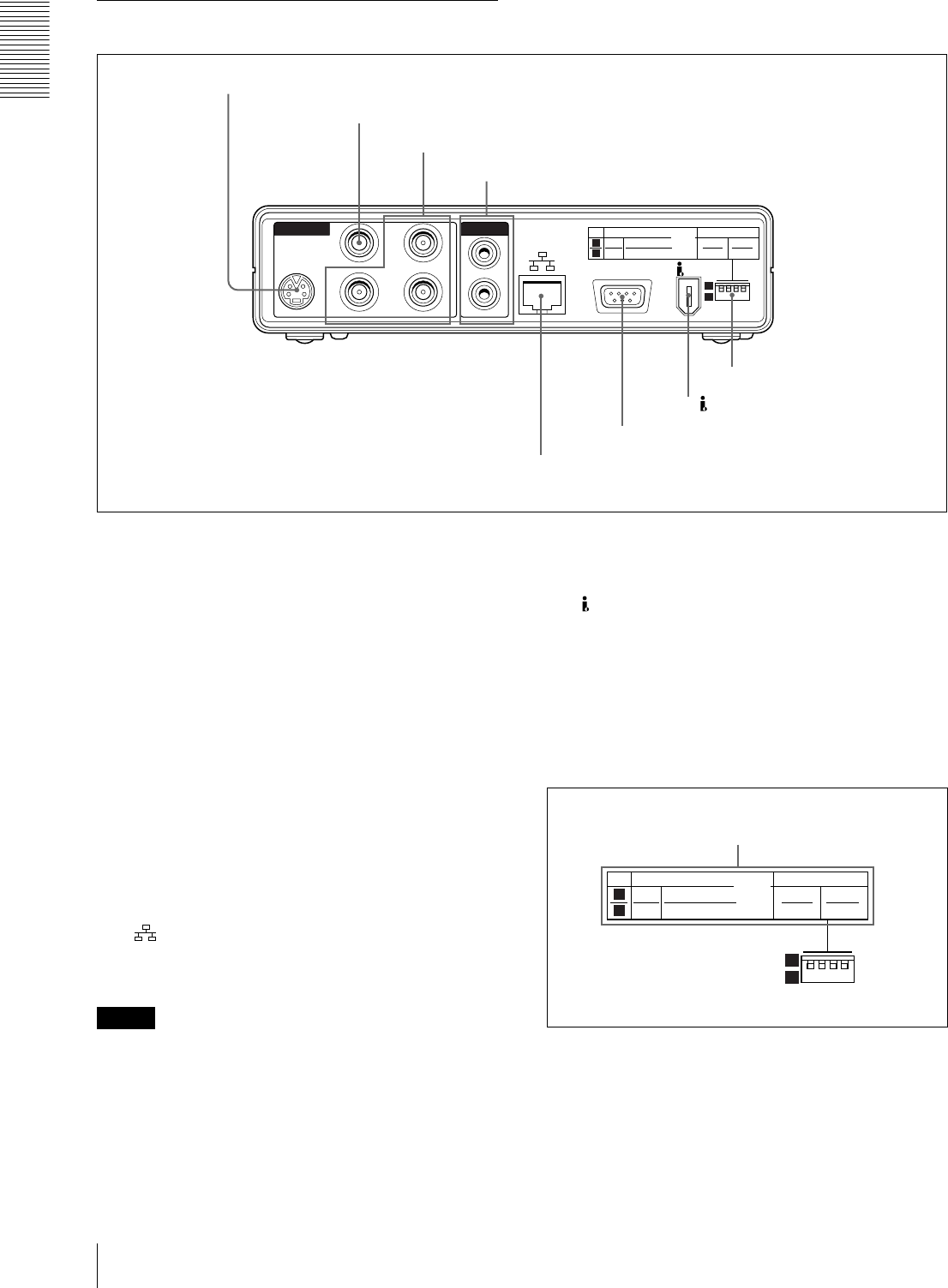
Main Unit Rear Panel
1 S-OUT (S-video output) connector (mini-DIN 4-
pin)
This outputs the playback video as an S-video signal.
2 COMOPOSITE connector (BNC type)
This outputs the playback video as an analog composite
signal.
3 G/Y, R/R
−
Y, B/B
−
Y (component video output)
connector (BNC type)
This outputs the playback video as an analog component
signal. A DIP switch setting controls whether this is Y/
R
−
Y/B
−
Y signals or RGB signals.
4 AUDIO OUT 1 and 2 connectors (pin jacks)
This outputs the playback audio as an analog signal. For
a stereo signal, connector 1 outputs the left channel, and
connector 2 the right channel.
5 (network) connector (RJ-45 modular jack)
This is a 100BASE-T connector for network (Ethernet)
connection.
Caution
When using a LAN cable: For safety, do not connect to
a connector for peripheral device wiring that might have
excessive voltage.
6 RS-232C/GPI (general-purpose interface)
connector (D-sub 9-pin, male)
Connect to the D-sub 9-pin connector of a plasma
display or video monitor.
7 S400(6-pin, IEEE 1394 compliant)
Connect to the i.Link connector of a computer.
8 DIP switches
The settings of the four switches relate to the video
format, component video output signal, and remote
controller. The diagram of DIP switch settings above the
switches shows the significance of the two positions
(“1” and “2”) for each switch.
VIDEO (video format/component video output
signal settings)
NTSC/PAL (leftmost switch): Select the video format.
COMPONENT/RGB (second switch from left):
Select output of a Y/R
−
Y/B
−
Y signal or RGB signal
from the G/Y, R/R
−
Y, B/B
−
Y connector.
AUDIO OUT
VIDEO OUT
RS-232C/GPI
COMPOSITE
1
S400
VIDEO IRD REMOTE
NTSC
PAL
1
2
S-OUT
G/Y
B/
B-Y
R/
R-Y
2
1
2
COMPONENT
RGB
ON
OFF
1
2
1 S-OUT connector
2
COMOPOSITE connector
3
G/Y, R/R
−
Y, B/B
−
Y connector
4 AUDIO OUT 1 and 2 connectors
5
Network connector
6
RS-232C/GPI connector
7
S400 connector
8 DIP switches
VIDEO IRD REMOTE
NTSC
PAL
1
2
1
2
COMPONENT
RGB
ON
OFF
1
2
DIP switch setting diagram