


Handbook for SXV-M5C Issue 1 August 2004
20
across the aperture of your telescope and point the instrument high in the sky, to avoid
any gradient in the light near the horizon. Now take several images with exposure
times adjusted to give a bright, but not overloaded, picture. Averaging flat field
together is a good way to reduce their noise contribution and so recording 4, or more,
images is a good idea.
To use your flat fields, they must first have a dark frame subtracted. Although this
may appear to be unimportant with such brightly lit and short exposures, there is the
‘bias offset’ of the camera in each image and this can produce an error in the final
correction. As we are mainly interested in the bias, any very short exposure dark
frame will give a good result. The dark subtracted images should then be averaged
together before use.
After the above procedures have been executed, the flat field will be ready for use.
Load up your image for processing, subtract the dark frame and then select ‘Apply
flat field’ in the ‘Merge’ menu. The result should be an image with very little sign of
the original artefacts.
********************************************************************
The accessory ports
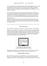
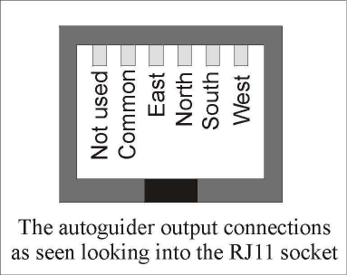
The SXV-M5C is provided with two ports for use with accessories. The Autoguider
output port is a 6 way RJ11 socket, which is compatible with the standard autoguider
input of most telescope mounts. It provides 4 active-low opto-isolator outputs and a
common return line, capable of sinking a minimum of 5mA per output. This socket
may be used for telescope control if the SXV-M5C is employed as an autoguider, but
is primarily intended to be the control output for the optional add-on autoguider
camera head, available for use with the SXV-M5C.
The high density parallel port socket provides both control and power for the add-on
autoguider, but also includes a pair of serial ports for use with other devices.
Using the built-in serial ports
The SXV-M5C incorporates two fast serial ports for use with external accessories.
The ports are available on 5 pins of the 18 way connector that is provided for the
autoguider and may be accessed by plugging in a ‘serial port divider box’. The divider