


33
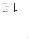
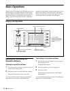
Location and Function of Controls
i Control knobs
The knobs are called the control 1, 2, 3, and 4 knob from
the top. These are for adjusting the values of parameters
displayed on the right of the display window. The function
of each knob depends on the operation software used.
For details, refer to the User’s Guide of the Operation
Software used.
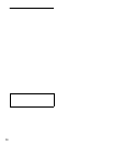
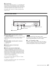
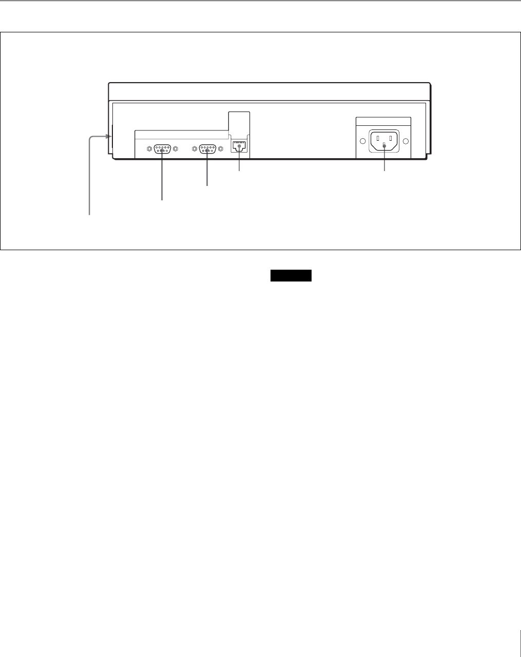
Rear and Side Panels
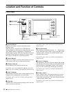
a EXT PANEL2 (extension panel 2) connector
(20-pin, side panel)
For future use. The connector has a power-supply pin (500
mA/5V). Remove the cover if you wish to use this
connector.
b EXT PANEL1 (extension panel 1) connector
(D-sub, 9-pin)
For future use.
c RS-232C connector (D-sub, 9-pin)
For maintenance.
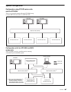
d DATA LAN connector (RJ-45, 8-pin)
Connect to the Ethernet
1)
switch. The network is
configured with PFV-SP-series IF processor and center
control panel of the MVS-8000 system connected to the
Ethernet switch, which enables communication among
connected units. As for the Ethernet switch you can use,
consult your Sony representative.
1) Ethernet is a trademark of XEROX Corporation.
For connection with the Ethernet switch, see “System
Configuration” on page 31.
For details on the Ethernet switch, refer to the instruction
manual of the Ethernet switch.
Caution
When using the DATA LAN connector cable:
For safety, do not connect to the connector for peripheral
device wiring that might have excessive voltage.
e - AC IN connector (3-pin)
Connect to a power source of 100 to 240 V AC using a
power cord (optional). Be sure to use a power cord that
satisfies the regulations of the country in which used.
RS-232C
EXT
PANEL1
DATA
LAN
-AC IN
1EXT PANEL2 connector
2EXT PANEL1 connector
3RS-232C connector
4DATA LAN connector 5-AC IN connector