


LZT 123 1836 45
5.8.2.1 Power On Timing
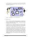
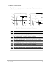
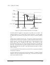
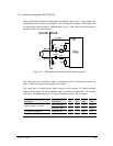
Figure 5.8-2 Power On timing using PON_L as an example
The GS64 power On sequence is shown above using PON_L as an example. The
significant signals are VCC, P_ON and VREF, shown by solid lines. The other signals
(in dashed lines) are internal to the module and are shown for reference purposes
only.
Initially, power is supplied to the VCC pins. The presence of power raises the PON_L
through a pull-up resistor to VCC potential. In order to power the module, PON_L is
pulled to ground. Once PON_L has been held low for 125ms (denoted by t
1
) the
primary LDOs power up, including the VREF output. VREF exceeds it’s reset
threshold approx 500µs later, then 250ms afterwards (denoted by t
2
) the
RESET
line
goes high. The microprocessor can latch the power-on state by setting the power
keep
(PWR_KEEP)
high after the
RESET
goes high and before the power on (PON_L)
signal is released.
It is recommended that P_ON is held low for at least 450ms to guarantee completion
of the power up sequence.
The PON_H signal has a similar effect at the point of assertion. The power-on timing
sequence is the same, provided PON_H remains high. PON_H has to remain high in
order for the module to function.