


LZT 123 1836 71
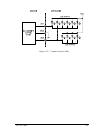
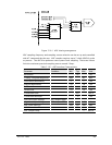
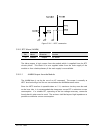
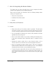
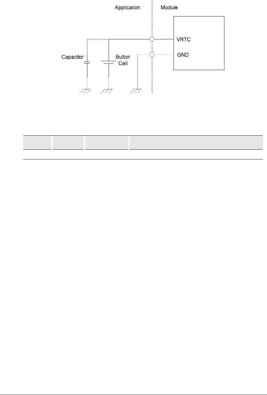
Figure 5.20-1 VRTC connection
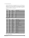
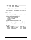
5.20.2 RTC Alarm (ALARM)
Pin Name Direction Function
32 ALARM Output RTC Alarm
The Alarm output is logic output from the module which is supplied from the RTC
circuitry block. This block is in turn supplied either from the main supply of the
module or from a backup battery if the main supply is not available.
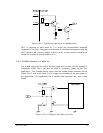
5.20.2.1 ALARM Output from the Module
The ALARM time is set by the use of an AT-command. The output is normally at
VRTC level and will go low for one second when the ALARM becomes active.
Since the VRTC interface is operable down to 1.1V, transistor circuitry must be used
on the host side. It is recommended that integrators use an FET to minimize current
consumption. If a suitable FET, operating at the low voltage necessary, cannot be
found then bi-polar must be used. The resistors shall be kept as high impedance as
possible to minimize current consumption.