11
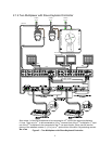
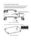
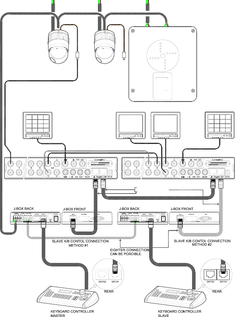
2.1.4 Two Multiplexer with Slave Keyboard Controller
SPOT MONITORSPOT MONITOR
RS-485(-) PIN No.5
RS-485(+) PIN No.4
BNC
1ST MULTIPLEXER
FOR SLAVE K/B1ST MAIN MONITOR
BNC
2ND MULTIPLEXER
2ND MAIN MONITOR
FOR MASTER K/B
BNC
POWER
AC 24V
AL5
AL6
GND
AL7
AL8
GND
COM3
NC3
NO3
COM4
NC4
NO4
AL1
GND
AL2
AL3
GND
AL4
COM1
COM2
NO1
NC1
NO2
NC2
AC+
RX-(TX-)
RX+(TX+)
AC-
(RX-)
FGND
AC+
AC-
(RX+)
GND
RS-485
(RS-422)
(RX+)
(RX-)
RX+(TX+)
RX-(TX-)
AC 24V
POWERPOWER
AC 24V
BNC
AWG # 24
Spot output 1 of the first multiplexer to be connected to 16
th
input of the second multiplexer.
n: User, Spot out of n
th
to be connected to (15-n)
th
camera input of the 2
nd
multiplexer. n
th
spot
out of the 2
nd
multiplexer to be connected to the n
th
use spot monitor. Each user will see the
picture of the selected camera (1~(31-n)) on n
th
spot monitor of the Mux 2 by selecting camera
No.+Cam.
Figure 5 – Two Multiplexer with Slave Keyboard Controller


