12 REFERENCE & INSTALLATION MANUAL
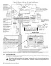
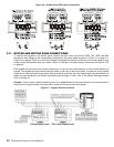
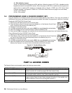
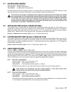
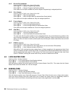
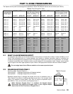
Figure 2.6: Double Zone (ATZ) Input Connections
2.11 KEYPAD AND KEYPAD ZONE CONNECTIONS
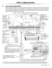
To connect the keypads to the control panel, remove the back cover and wire the GRN, YEL, RED, and BLK
terminals of each keypad to the corresponding terminals on the control panel as shown in Figure 2.1 on page 7 or
Figure 2.2 on page 8. There is no limit to the number of keypads that can be connected to the control panel so long
as the current consumption does not surpass 700mA. For details on Keypad Tamper Supervision see section 10.8
on page 44.
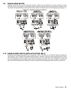
Each keypad has one zone input terminal, allowing you to connect one motion detector or door contact directly to a
keypad. The keypad can then communicate the status of the zone to the control panel. A maximum of two keypad
zones can be used with each control panel. After connecting the device, the zone's parameters must be defined. For
details on zone recognition and Zone Programming refer to page 19. Also, refer to the feature Reassign Keypad
Zone 2 on page 19.
Example: A door contact located at the entry point of an establishment can be wired directly to the input terminal of
the entry point keypad instead of wiring the door contact all the way to the control panel.
Figure 2.7: Keypad Zone Connections


