


Single-Chip Ethernet Controller with HP Auto-MDIX Support and PCI Interface
Datasheet
Revision 1.22 (09-25-08) 58 SMSC LAN9420/LAN9420i
DATASHEET
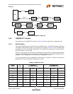
The Filter i Byte Mask defines which incoming frame bytes Filter i will examine to determine whether
or not this is a wakeup frame. Table 3.15, describes the byte mask’s bit fields.
The Filter i command register controls Filter i operation. Table 3.16 shows the Filter I command
register.
The Filter i Offset register defines the offset in the frame’s destination address field from which the
frames are examined by Filter i. Table 3.17 describes the Filter i Offset bit fields.
The Filter i CRC-16 register contains the CRC-16 result of the frame that should pass Filter i.
Table 3.18 describes the Filter i CRC-16 bit fields.
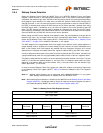
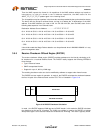
Table 3.15 Filter i Byte Mask Bit Definitions
FILTER i BYTE MASK DESCRIPTION
BITS DESCRIPTION
31 RESERVED
30:0 Byte Mask: If bit j of the byte mask is set, the CRC machine processes byte pattern-offset + j of
the incoming frame. Otherwise, byte pattern-offset + j is ignored.
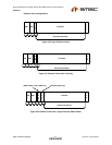
Table 3.16 Filter i Command Bit Definitions
FILTER i COMMANDS
BITS DESCRIPTION
3 Address Type: Defines the destination address type of the pattern. When bit is set, the pattern
applies only to multicast frames. When bit is cleared, the pattern applies only to unicast frames.
2:1 RESERVED
0 Enable Filter: When bit is set, Filter i is enabled, otherwise, Filter i is disabled.
Table 3.17 Filter i Offset Bit Definitions
FILTER i OFFSET DESCRIPTION
BITS DESCRIPTION
7:0 Pattern Offset: The offset of the first byte in the frame on which CRC is checked for wakeup frame
recognition. The MAC checks the first offset byte of the frame for CRC and checks to determine
whether the frame is a wakeup frame. Offset 0 is the first byte of the incoming frame's destination
address.