


―――――――――――――――――――――――――――――――――――――――――――――――――――――――――――――――――――――――――――――
STAR Line Mode Command Specifications 1-1
1. INTERFACE CONFIGURATION
1.1. RS-232 Serial Interface
1.1.1. Specifications (Conforming to RS-232)
Rating: RS-232C
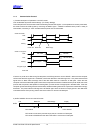
Synch method: Start-Stop synchronization method
Handshake: DTR mode
Baud rates: 4800, 9600, 19200, 38400 bps (Set by DIP switches)
Bit length: 7, 8 bits (Set by DIP switches)
Parity: Yes/No (Set by DIP switches)
Parity bit: Odd/even (Set by DIP switches)
Stop bit: 1 bit (Fixed)
Signal polarity: Mark = logic 1 (-3 to -15 V)
Space = logic 0 (+3 to +15 V)
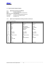
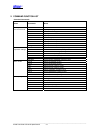
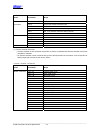
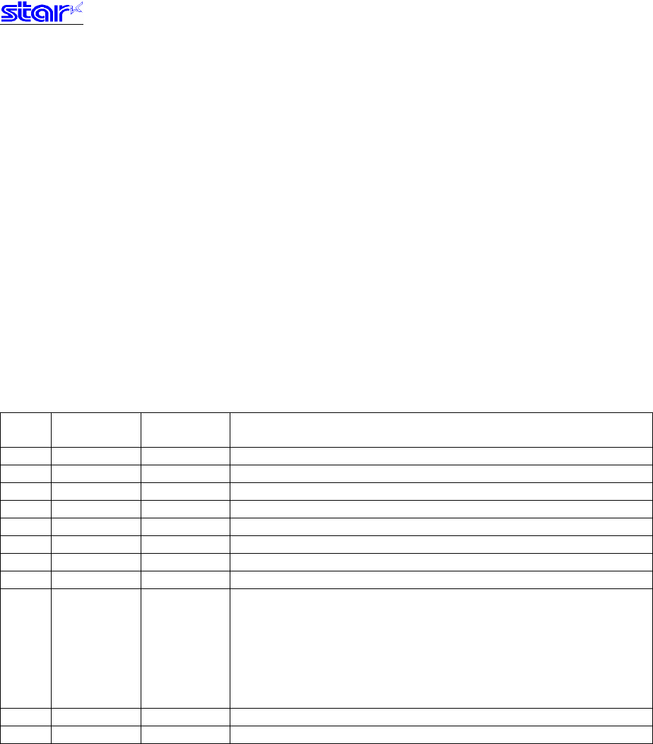
1.1.2. Signal array and explanations according to interface connector pin
<Signal Array and Functions>
Pin
No.
Signal Name Signal
Direction
Remarks
1 FG - Frame ground
2 TXD OUT Transmission data
3 RXD IN Reception data
4 RTS OUT Same as DTR
5 N.C - Not used
6 DSR IN Not used
7 SG - Signal ground
8-19 N.C - Not used
20 DTR OUT Data terminal ready signal (SPACE: printer is ready to receive.)
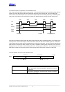
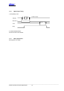
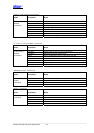
1) When in DTR mode:
When printer is ready to receive data: SPACE
2) When in XON/XOFF mode:
Always SPACE except in the following conditions.
1. Until communication is possible after a reset.
2. When test printing
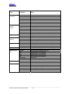
21-24 N.C Signal ground
25 /INIT IN Signal ground