


– 87 –
APPENDIX
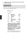
Appendix A: Serial Interface
14
113
25
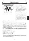
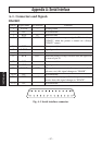
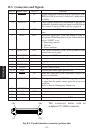
A-1. Connectors and Signals
RS-232C
Pin no. Signal name I/O direction Function
1 F-GND — Frame ground
2 N/C Not connected
3 RXD IN Received data
4 RTS OUT Data transmission request signal. This is always
“SPACE” when the printer is turned on. (Always
“SPACE” status)
5-6 N/C Not connected
7 S-GND — Signal ground
8-10 N/C Not connected
11 RCH OUT When the printer is ready to receive data, the signal line
is same as pin 20.
12 N/C Not connected
13 GND — Signal ground
14 FAULT OUT When printer error occurs (such as paper out, mechani-
cal error, etc.) this signal changes to “MARK”.
15-19 N/C Not connected
20 DTR OUT Data terminal ready signal. When the printer is ready to
receive data, this signal changes to “SPACE”.
21-25 N/C Not connected
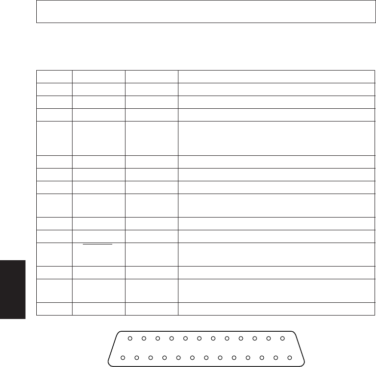
Fig. A-1 Serial interface connector