


– 93 –
APPENDIX
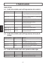
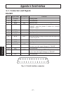
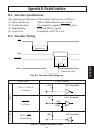
B-3. Connectors and Signals
Pin No. Signal Name IN/OUT Function
1 STROBE IN Signals when data is ready to be read. Signal goes from
HIGH to LOW (for at least 0.5 microsec.) when data is
available.
2-9 DATA1-8 IN These signals provide the information of the first to
eighth bits of parallel data. Each signal is at HIGH level
for a logical 1 and at a LOW level for a logical 0.
10 ACK OUT A 9 microsecond LOW pulse acknowledges receipt of
data.
11 BUSY OUT When this signal goes LOW, the printer is ready to
accept data. When the printer is in one of the conditions
below. “HIGH” is set.
1. Data being entered.
2. Off line.
3. Error condition.
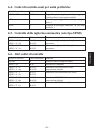
12 PAPER OUT OUT This signal is normally LOW. It will go HIGH if the
printer runs out of paper.
13 SELECTED OUT This signal is HIGH when the printer is online.
14-15 N/C Not connected
16
SIGNAL GND
Signal ground.
17
CHASSIS GND
Chassis ground, isolated from logic ground.
18 +5VDC +5VDC (Max 50 mA)
19-30 GND Twisted pair return signal ground level.
31 RESET IN When this signal goes LOW, the printer is reset to its
power-on condition.
32 ERROR OUT This signal is normally HIGH. This signal goes LOW
to signal that the printer cannot print due to an error
condition.
Refer to Item 8-4 Emergency Suspension.
33 EXT GND External ground.
34 OUT1 OUT Unused.
35 N/C Not connected
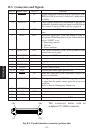
36 The printer side is always set to HIGH.
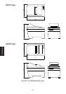
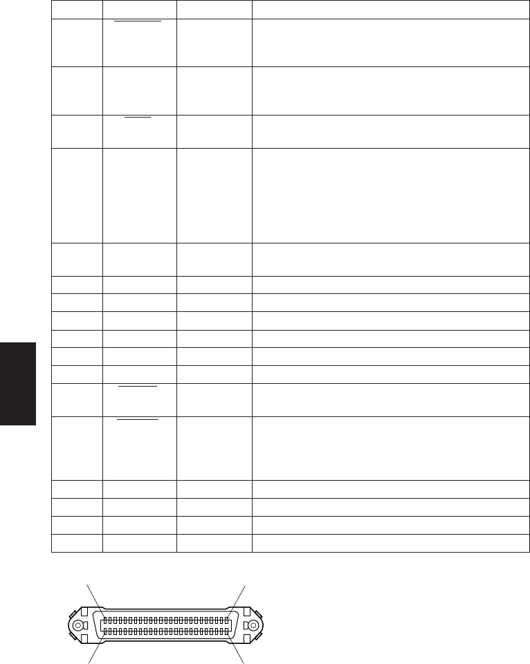
This connector mates with an
Amphenol 57-30360 connector
Fig. B-3. Parallel interface connector (printer side)
(19) (36)
(1) (18)