


Thales Computers 2-11 CPMC-1553R User’s Guide, CA.DT.356-0e
2.2.3 PCI I/O Space
The PCI I/O space is not utilized by the CPMC-1553R board.
2.2.4 Interrupt A (INTA*)
The CPMC-1553R board generates INTA* on the PCI Bus when either of the Mini-ACE devices generates
an interrupt or an interrupt occurs from one of the user-defined input lines. The interrupt conditions are
configurable through software.
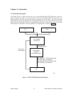
2.3 MIL-STD-1553B Bus
Each MIL-STD-1553B bus is implemented using an ILC-DDC Mini-ACE device with 64kB x 16 of shared
RAM. This device can be set up, through software, to operate as a BC, RT, or MT. Each Mini-Ace is
wired to operate in buffered mode, with a 16-bit data transfer rate. Each bus can be either direct coupled or
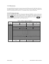
transformer coupled. Careful consideration should be given to the routing of the MIL-STD-1553B
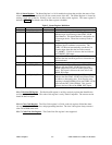
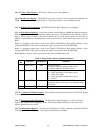
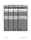
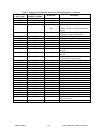
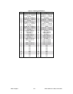
differential signal pairs. All MIL-STD-1553B signals are routed off-board via the Pn4 connector. The
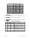
signal definitions for the Pn4 connector are defined in Table 11. Pins that have no connection on the
CPMC-1553R board are defined as N/C.
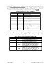
2.3.1 Signal Naming Convention
The MIL-STD-1553 signal pairs routed to the Pn4 connector use the following naming convention:
TX/RX-(letter)_(number)_(direct/trans)
TX/RX-(letter)_(number)*_(direct/trans)
The letter refers to channel A or B of a particular MIL-STD-1553B Bus. These correspond to channel A
and channel B on the ACE device.
The number refers to the ACE number. For a card using only one dual-redundant bus, only signals with a
1 in this location will be mapped to this connector.
The direct/trans refers to the type of coupling required for that signal pair: direct or transformer coupled.
The transformer-coupled signal pair for channel A on a board using only one Mini-ACE device would be
TX/RX-A_1_TRANS and TX/RX-A_1*_TRANS.
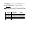
2.3.2 Remote Terminal Address
The RT address is configurable via the Pn4 connector. The RTAD[4:0] and RTADP signals are pulled up
on the CPMC-1553R board. A ground signal is provided with each set of RT address signals, on Pn4, to
allow the user to make any of these signals low.
The RT address may be configured to latch the RTAD[4:0] and RTADP signals with a software command
or to continuously track the RTAD[4:0] and RTADP signals. The default for the CPMC-1553R board is to
latch the RT address (RT_AD_LAT to the Mini-ACE pulled high).