


Thales Computers 1-3 CPMC-1553R User’s Guide, CA.DT.356-0e
1.3 CPMC-1553R Options
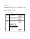
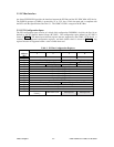
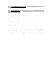
Figure 2 shows the standard options available for the CPMC-1553R.
CPMC-1553R-__ __
Environment
Industrial/-SA.................................................................................I
Rugged/-RA....................................................................................R
Militarized/-RC ..............................................................................M
Channels
1 Channel..............................................................................................1
2 Channels............................................................................................2
Figure 2. CPMC-1553R Standard Options
1.4 Installation and Configuration
1.4.1 Precautions
Electrostatic discharge can damage many of the components of the CPMC-1553R. Therefore, it should be
kept in its protective antistatic bag until it is ready to be configured and installed. During installation or
whenever the CPMC-1553R is removed from the bag, it is important to follow proper grounding
procedures. Such procedures include use of an antistatic workstation, an operator wrist strap, and a
grounded bench mat. Save the antistatic bag for use in storing or shipping the CPMC-1553R.
Closely inspect the board for any signs of shipment-related damages such as loose components or bent pins.
If any evidence of damage is discovered, please notify the carrier and Thales Computers immediately.
1.4.2 Installation
The CPMC-1553R board attaches to a PMC carrier board. The attaching hardware for the CPMC-1553R
board is included with your order.
Attach the CPMC-1553R board to the PMC carrier board according to the following instructions.
a. Remove the PMC carrier board from the chassis.
b. Align the PCI connectors on the component side of the CPMC-1553R board with the PCI connectors
on the component side of the PMC carrier board. Press them together so that the friction from the pins
holds them together. After inserting the board make sure that the connectors have not shifted.
c. Insert the screws supplied with the board, through the bottom of the PMC carrier board and into the
standoffs attached to the CPMC-1553R.
d. For a conduction-cooled board, install the remaining screws through the CPMC-1553R into the
reinforcing bars on the PMC carrier board.
e. Insert the PMC carrier board back into the chassis making sure it is plugged into the backplane.
f. Turn on the system power.