


Version 3.1-en Solaris 10 Container Guide - 3.1 4. Best Practices Effective: 30/11/2009
administrator. With the software products described here, the requirements with respect to
visualization and flexibilization of containers right up to disaster recovery concepts can be covered
completely.
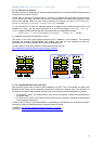
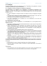
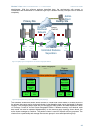
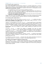
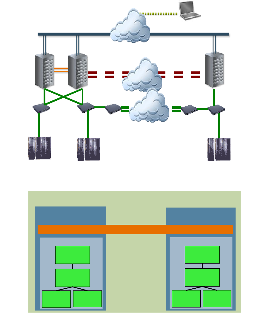
The hardware architecture shown above consists of a dual-node cluster made of SF6900 servers in
the primary data center and a single-node cluster in the alternative data center designated for disaster
recovery. The storage systems used are Sun StorageTek 9990 systems and data replication is done
via Truecopy. Control is via Sun Cluster Geographic Edition. If disaster recovery is not desired, each
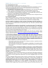
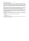
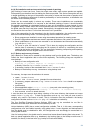
data center can also be operated independently. In the resource group topology shown above, the
active cluster manages a container. The passive cluster is used for disaster recovery purposes. The
clusters form a partnership and manage the resource groups in a so-called protection group.
48
Figure 25: [tf/du] Typical configuration: Sun Cluster Geographic Edition
Primary Site
Backup Site
Unlimited Distance
Separation
Admin.
Client
Optional
Heartbeat
Network
Router
DWDM
DWDM
DWDM
9990
9990
9990
SE
Network
FC
Switch-8
SE
Network
FC
Switch-8
SE
Network
FC
Switch-8
Figure 26: [tf/du] Resource groups and protection group topology
Sun Cluster Geographic
Edition
Active
Passive
Sun Cluster
Hamburg
Container rg
Container
Agent
HAStorage
Plus
Container
Agent Applic.
Logical
Host
Sun Cluster
Munich
Container protection group
Container rg
Container
Agent
HAStorage
Plus
Container
Agent Applic.
Logical
Host