


65
APPENDIX
C
Connections Within the Cluster
Platform 4500/3
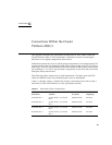
This appendix describes the preinstalled arrangement of some cables within the
Cluster Platform 4500/3. This information is provided to assist in restoring the
hardware to its original configuration after service.
Cables that connect the servers to their storage components are run between the I/O
system boards on the Sun Enterprise 4500 system cluster nodes to the FC-AL hubs or
disk arrays. The I/O system boards for the Sun Enterprise 4500 system cluster nodes
are numbered 1, 3, 5, and 7, top to bottom, respectively, on the rear sides of the Sun
Enterprise 4500 system nodes.
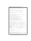
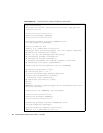
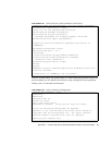
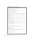
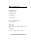
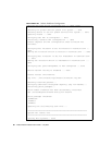
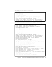
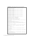
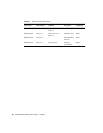
The following tables contain lists of cable destinations. The fiber optic and SCSI
cables are labeled at each end, identifying the source to destination.
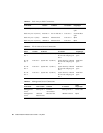
TABLE C-1 through TABLE C-8 identify the primary connections from eri0 on node 1
and node 2 to the NAFO failover on your production network.
TABLE C-1 Boot Disk to Server Connections
From Device To Device To Location
Cable
Length/Type
D130 disk No. 1 System node 1, I/O board
No. 1
Onboard SCSI 2m SCSI
D130 disk No. 2 System node 1, I/O board
No. 3
Onboard SCSI 2m SCSI
D130 disk No. 3 System node 2, I/O board
No. 1
Onboard SCSI 2m SCSI
D130 disk No. 4 System node 2, I/O board
No. 3
Onboard SCSI 2m SCSI