


5-12
SUPERSERVER 1018D-73MTF User's Manual
5-8 Connector Defi nitions
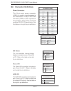
Processor Power
Pin Defi nitions (JPW2/JPW3)
Pins Defi nition
1 through 4 Ground
5 through 8 +12V
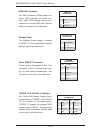
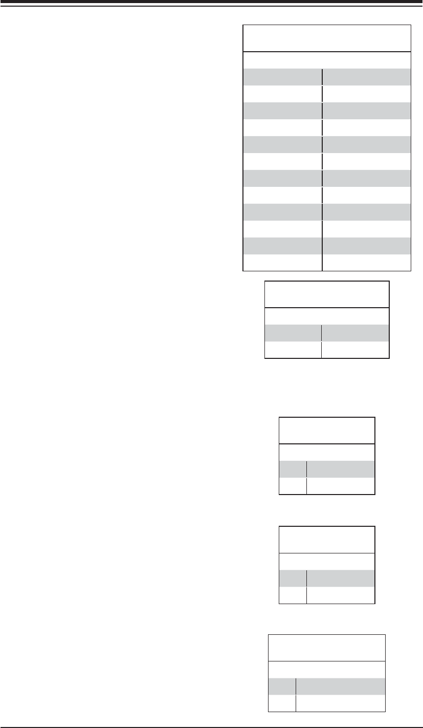
ATX Power 24-pin Connector
Pin Defi nitions (JPW1)
Pin# Defi nition Pin # Defi nition
13 +3.3V 1 +3.3V
14 -12V 2 +3.3V
15 COM 3 COM
16 PS_ON 4 +5V
17 COM 5 COM
18 COM 6 +5V
19 COM 7 COM
20 Res (NC) 8 PWR_OK
21 +5V 9 5VSB
22 +5V 10 +12V
23 +5V 11 +12V
24 COM 12 +3.3V
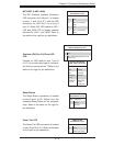
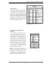
Power LED
The Power LED connection is located on
pins 15 and 16 of JF1. Refer to the table
on the right for pin defi nitions.
Power LED
Pin Defi nitions (JF1)
Pin# Defi nition
15 +3.3V
16 Power LED
HDD LED
The HDD LED connections are located on
pins 13 and 14 of JF1. Attach a cable here
to indicate HDD activity. See the table on
the right for pin defi nitions.
HDD LED
Pin Defi nitions (JF1)
Pin# Defi nition
13 3.3V SB/UID Switch
14 HD Active
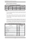
Power Connectors
The 24-pin main power connector
(JPW1) is used to provide power to
the motherboard. The 8-pin CPU PWR
connector (JPW2) is also required for
the processor. These power connectors
meet the SSI EPS 12V specifi cation. See
the tables on the right for pin defi nitions.
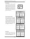
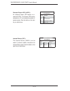
NMI Button
The non-maskable interrupt button
header is located on pins 19 and 20
of JF1. Refer to the table on the right
for pin defi nitions.
NMI Button
Pin Defi nitions (JF1)
Pin# Defi nition
19 Control
20 Ground