


Chapter 5: Advanced Motherboard Setup
5-13
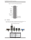
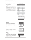
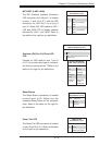
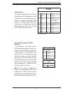
NIC1/NIC2 (LAN1/LAN2)
The NIC (Network Interface Controller)
LED connection for LAN port 1 is located
on pins 11 and 12 of JF1, and the LED
connection for LAN Port 2 is on pins 9
and 10. Attach NIC LED cables to NIC1
LED and NIC2 LED to display network
activities for LAN 1 and LAN2. Refer to
the table on the right for pin defi nitions.
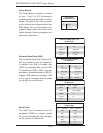
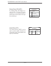
Overheat (OH)/Fan Fail/Front UID
LED
Connect an LED cable to pins 7 and 8
of JF1 to provide warnings of overheat,
fan failure or power failure. TRefer to the
table on the right for pin defi nitions.
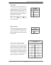
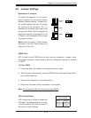
Reset Button
The Reset Button connection is located
on pins 3 and 4 of JF1. Attach it to a the
hardware Reset Button on the computer
case. Refer to the table on the right for
pin defi nitions.
Reset Button
Pin Defi nitions (JF1)
Pin# Defi nition
3 Reset
4 Ground
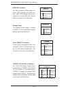
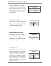
Power Fail LED
The Power Fail LED connection is located
on pins 5 and 6 of JF1. Refer to the table
on the right for pin defi nitions.
PWR Fail LED
Pin Defi nitions (JF1)
Pin# Defi nition
5 3.3V
6 PWR LED Status
GLAN1/2 LED
Pin Defi nitions (JF1)
Pin# Defi nition
9 Vcc
10 NIC 2 Link/Acitivty
LED
11 Vcc
12 NIC 1 Link/Acitivty
LED
OH/Fan Fail/ PWR Fail/Blue_UID
LED Pin Defi nitions (JF1)
Pin# Defi nition
7 Vcc
8 Red_LED-Cathode/OH/Fan Fail/
Power Fail
OH/Fan Fail/PWR Fail
LED Status (Red LED)
State Defi nition
Off Normal
On Overheat
Flashing
1 Hz
Fan Fail
Flashing
1/4 Hz
Redundant
Power
Supply Fail