


Chapter 5: Advanced Motherboard Setup
5-17
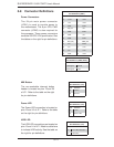
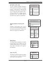
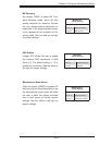
Ethernet Ports
Two Gigabit Ethernet ports (LAN1/2)
are located on the I/O backplane on the
motherboard to provide internet con-
nections. In addition, a dedicated IPMI
LAN port is included located above the
USB ports on the backplane to provide
KVM support for IPMI 2.0. All these
ports accept RJ45 type cables.
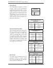
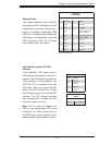
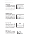
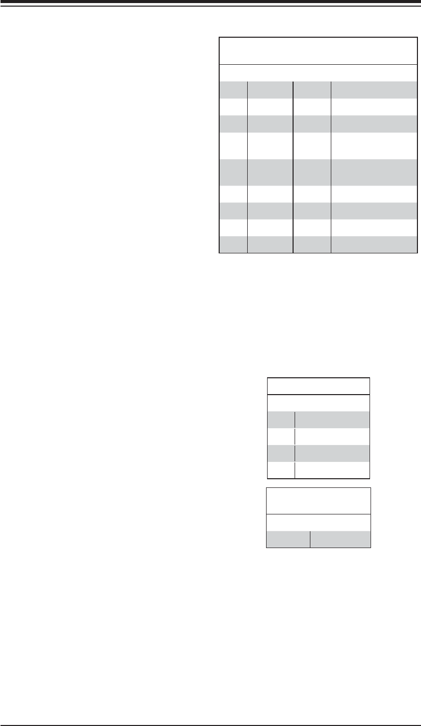
LAN Ports
Pin Defi nition
Pin# Defi nition
1 P2V5SB 10 SGND
2 TD0+ 11 Act LED
3 TD0- 12 P3V3SB
4 TD1+ 13 Link 100 LED (Yel-
low, +3V3SB)
5 TD1- 14 Link 1000 LED (Yel-
low, +3V3SB)
6 TD2+ 15 Ground
7 TD2- 16 Ground
8 TD3+ 17 Ground
9 TD3- 18 Ground
(NC: No Connection)
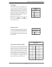
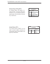
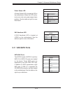
Unit Identifi er Switch/UID LED
Indicator
A Unit Identifi er (UID) switch and an
LED indicator are located on the moth-
erboard. The UID switch is located next
to the VGA port on the backplane. The
UID LED (LE4) is located next to the
UID switch. When you press the UID
switch, the UID LED will turn on. Press
the UID switch again to turn off the LED
indicator. The UID Indicator provides
easy identifi cation of a system unit that
may be in need of service.
Note: UID can also be triggered via
IPMI on the motherboard. For more
information on IPMI, please refer to
the IPMI User's Guide posted on our
website @http://www.supermicro.com.
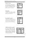
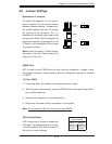
UID Switch
Pin# Defi nition
1 Ground
2 Ground
3 Button In
4 Ground
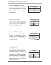
UID LED
Status
Color/State Status
Blue: On Unit Identifi ed