


Chapter 2: Installation
2-13
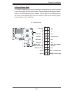
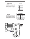
FP Power Butt
o
OH/Fan Fail/
PWR Fail/UID LED
1
NIC1 LED
FP Reset Butt
o
2
HDD LED
Power LED
Reset
PWR
Vcc
UID Switch/Vcc
Vcc
Blue_LED_Cathode
(UID)/Vcc
Ground
Ground
1920
Vcc
X
Ground
NMI
X
Vcc
PWR Fail LED
NIC2 LED
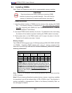
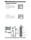
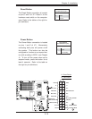
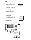
Power Button
The Power Button connection is located
on pins 1 and 2 of JF1. Momentarily
contacting both pins will power on/off
the system. This button can also be
confi gured to function as a suspend but-
ton (with a setting in BIOS - see Chapter
4). To turn off the power when set to
suspend mode, press the button for at
least 4 seconds. Refer to the table on
the right for pin defi nitions.
Power Button
Pin Defi nitions (JF1)
Pin# Defi nition
1 Signal
2 +3V Standby
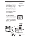
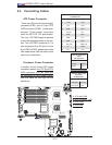
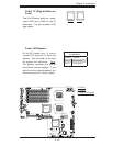
Reset Button
The Reset Button connection is located
on pins 3 and 4 of JF1. Attach it to the
hardware reset switch on the computer
case. Refer to the table on the right for
pin defi nitions.
Reset Button
Pin Defi nitions (JF1)
Pin# Defi nition
3 Reset
4 Ground
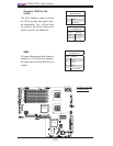
A. Reset Button
B. PWR Button
A
B
J
W
O
R
1
C
O
M2
J
7
J
BT1
J
W
O
L1
J
P
L1
J
P
L2
J
3
0
J
L1
J
O
H1
J
D
1
Fan2
LE1
J
F1
FP
C
T
R
L
J
P
W
1
J
1
7
LE2
SW1
J11
I2
C
1
I2
C
2
J
P
G1
Rear UID
E
S
1
0
0
0
V
ide
o
C
T
R
L
I
n
tel
E
S
B
2
(
So
u
th
B
rid
g
e)
US
B
4
J
W
D
J
K
1
USB2
/
3
J
1
8
S
MB
C
PU
1
J
P
W
3
COM1
VGA
LAN1
LAN2
J
2
8
SXB2
:
P
C
I
-
E
x8
SXB1
:
P
C
I-E
x1
6
P
C
I-X
1
3
3
MHz
(Nor
th Bri
d
ge
)
Video
Memo
ry
X7DBU
J
2
9
Fan4
Fan8
C
P
U
F
A
N
2
Fan3
Fan1
2
0
-P
i
n
Main
P
W
R
J
P
W
2
4
-P
in
P
W
R
8
-P
in
P
W
R
Fan7
C
P
U
Fan1
P
W
R
SMB
Fan5
Fan6
Buzz
e
r
SP1
J9B2
J9B1
J8B3
J8B2
J8B1
J7B3
J7B2
J7B1
D
IMM4
B
S
GP
IO
1
S
GP
IO
2
J
2
7
UIO
P
W
R
LA
N
C
T
R
L
J
LA
N
2
J
LA
N
1
J
1
5
J
C
O
M
1
J
K
M1
Bank1
I-SA
T
A
0
I
-S
A
T
A
1
I-S
A
T
A
2
I
-S
A
T
A
3
I-SA
T
A
4
I-SA
T
A
5
BIO
S
J
2
2
Floppy
SIMSO
ID
E#
1
C
PU
2
J
P
1
D
IMM1
A
D
IMM1
B
D
IMM2
A
D
IMM2
B
D
IMM3
A
D
IMM3
B
D
IMM4
A
B
att
e
ry
Bank2
Bank3
Bank4
KB/MS
USB 0/1
J
5
J14
S
I/
O
I
nte
l
5
0
0
0
J
9