


2-14
X7DBU/X7DGU User's Manual
J
W
OR1
CO
M
2
J
7
J
BT
1
J
W
OL1
J
PL1
J
PL2
J
30
J
L1
J
OH1
J
D
1
F
an
2
LE
1
J
F
1
F
P
CT
RL
J
PW
1
J
17
LE2
SW1
J11
I2C1
I2C2
J
PG1
Rear UID
E
S
10
00
V
id
e
o
CT
RL
Inte
l
E
S
B
2
(S
outh B
ridge
)
US
B
4
J
W
D
J
K1
US
B2/3
J
1
8
S
MB
C
P
U1
JPW
3
COM1
VGA
LAN1
LAN2
J
28
S
XB2:
PCI-E
x8
S
XB1:
PCI-E
x16
PCI-X
133 M
Hz
(
Nor
t
h Br
idge)
Vid
e
o
M
e
m
o
r
y
X7DBU
J
29
F
an
4
F
an
8
CPU
F
A
N2
F
an
3
Fan1
20
-P
in
M
a
in
PW
R
J
PW
2
4-Pin
PW
R
8-Pin
PW
R
F
an
7
CPU
F
an
1
PW
R
S
M
B
Fa
n
5
Fa
n
6
Bu
zz
e
r
S
P1
J9B2
J9B1
J8B3
J8B2
J8B1
J7B3
J7B2
J7B1
D
IMM
4B
S
GPIO
1
S
GPIO2
J
27
UI
O
PW
R
LA
N
C
T
RL
J
LA
N2
J
LA
N
1
J
15
J
COM
1
J
KM1
Bank1
I-S
A
T
A
0
I-S
A
T
A
1
I-SA
T
A
2
I-
S
A
T
A
3
I-SA
T
A
4
I-
S
A
T
A
5
B
IO
S
J
22
F
lo
p
p
y
S
IM
S
O
ID
E
#
1
C
P
U2
J
P1
D
IM
M
1A
D
IMM
1B
D
IMM
2A
D
IMM
2B
D
IMM
3A
D
IMM
3
B
D
IMM
4A
Batt
e
r
y
Bank2
Bank3
Bank4
KB/MS
USB 0/1
J
5
J14
S
I/O
I
ntel 500
0
J
9
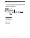
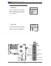
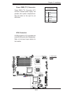
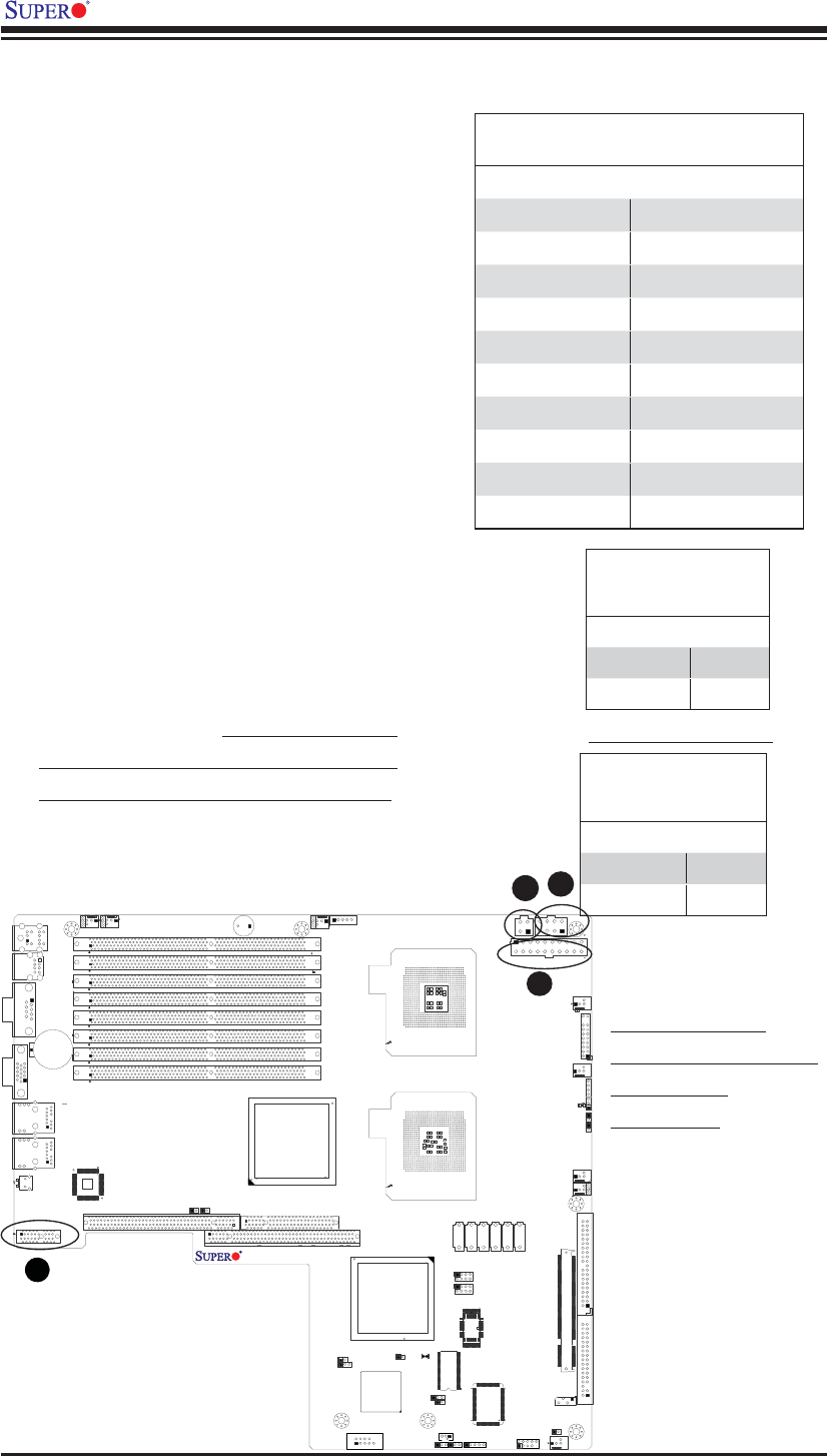
2-5 Connecting Cables
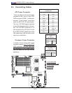
ATX Power Connector
There are a 20-pin main power supply
connector(JPW1) and an 8-pin CPU
PWR connector (JPW3) on the moth-
erboard. These power connectors
meet the SSI EPS 12V specifi cation.
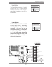
The 4-pin 12V PWR supply is required
to provide adequate power to the sys-
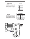
tem. The UIO PWR, located at J11, is
also required for the UIO slots. For the
8-pin PWR (JPW3), please refer to the
item listed below. See the table on the
right for pin defi nitions.
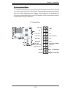
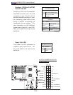
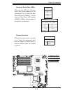
Processor Power Connector
In addition to the Primary ATX power
connector (above), the 12V 8-pin CPU
PWR connector at JPW3 must also
be connected to your power supply.
See the table on the right for pin
defi nitions.
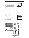
ATX Power 20-pin Connector
Pin Defi nitions
Pin# Defi nition Pin # Defi nition
11 +3.3V 1 +3.3V
12 -12V 2 +3.3V
13 COM 3 COM
14 PS_ON 4 +5V
15 COM 5 COM
16 COM 6 +5V
17 COM 7 COM
18 Res (NC) 8 PWR_OK
19 +5V 9 5VSB
20 +5V 10 +12V
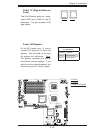
Required Connection
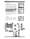
12V 4-pin Power Con-
nector
Pin Defi nitions
Pins Defi nition
1 and 2 Ground
3 and 4 +12V
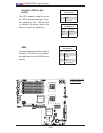
12V 8-pin Power CPU
Connector
Pin Defi nitions
Pins Defi nition
1 through 4 Ground
5 through 8 +12V
A. ATX Main PWR
B. 8-pin Processor PWR
C. 4-pin PWR
D. UIO PWR
A
B
C
D