


TANDBERG GW Dataport Command Interface User Guide
D13202 Rev 01 4
2. Connecting to the Dataport Command Interface through the
RS-232 port.
The RS-232 port is a 9-pin, female, D-sub connector located on the back of the GW. The port
is configured as a DCE (Data Communications Equipment). The RS-232 port is default set to
9600 baud, 8 databits, none parity and 1 stopbit from factory. The RS-232 port is also referred
to as the Dataport.
2.1. Hardware And Cabling
The pin outs for the RS-232 are defined in the following table (the DTE, Data Terminal
Equipment, could be a PC or other device capable of serial communication).
Pin no Signal Description Direction
1 CD Carrier detect To DTE
2 RD Receive data To DTE
3 TD Transmit data From DTE
4 DTR Data terminal ready From DTE
5 Ground
6 DSR Data set ready To DTE
7 RTS Ready to send From DTE
8 CTS Clear to send To DTE
9 RI Ring indicator To DTE
NOTE! A straight through cable should be used between the TANDBERG GW’s RS-232 port
and the DTE.
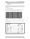
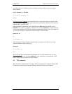
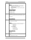
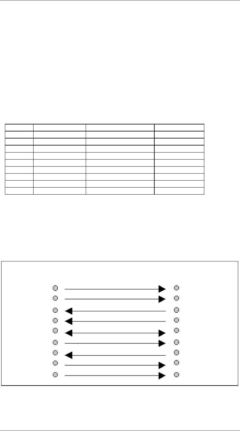
The figure below illustrates the recommended cable-wiring scheme for connecting the GW to
a PC through RS-232.
DTR and RTS are ignored. DSR, CD, and CTS are always asserted, while RI is not used.
TANDBERG GW PC
DCE, 9 pin DTE, 9 pin
1 CD 1 CD
2 RD 2 RD
3 TD 3 TD
4 DTR 4 DTR
5 GND 5 GND
6 DSR 6 DSR
7 RTS 7 RTS
8 CTS 8 CTS
9 RI 9 RI