


D14274.01—NOVEMBER 2008
48
T1
Administrator Guide
Contents Introduction Getting started About the menus About the settings Settings Library Cameras Appendices Contact us
Appendices
Line in
Rev.
Date
Prep.
Checked
Change
-
-
-
Telecom AS
-
-
-
-
-
-
-
-
-
-
-
-
-
-
-
-
-
-
Part weight:
Sheet size:
Scale:
Surface treatment
Specication:
Material
Tolerances
Unit:
European
projection
Sheet 1 of 1
All materials, nishes, and proccesses
must comply with the RoHS directives
Dimensions without paint or nish
Flame class requirement: -
Processes
Type:
Manufacturer:
Type number:
Thickness:
Color:
Surface:
Glossiness:
Flame class:
UL reference:
3D CAD model le 116805
rev. 00Z+ is master
Saturn C70 Unit
116805 rev.
3172g
A3
mm
1:5
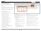
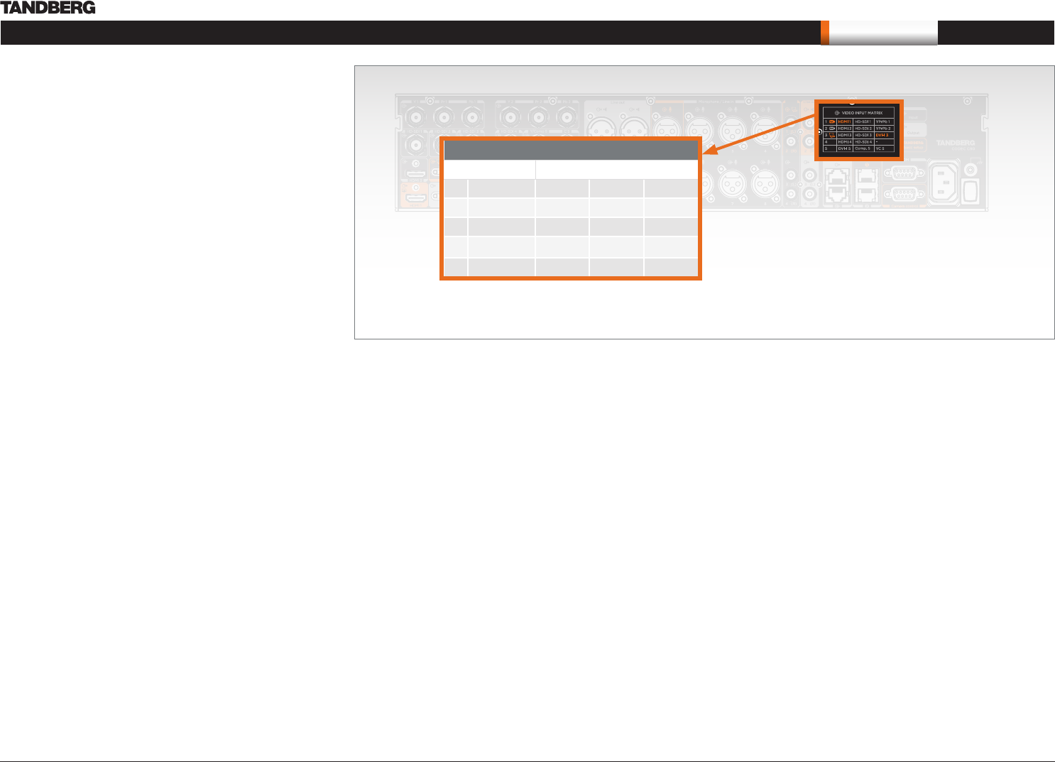
Video input matrix
Input Sources Connector Name
1 1st Camera HDMI 1 HD-SDI 1 YPrPb 1
2 2nd Camera HDMI 2 HD-SDI 2 YPrPb 2
3 PC HDMI 3 HD-SDI 3 DVI-I 3
4 HDMI 4 HD-SDI 4 –
5 DVI-I 5 Comp. 5* YC 5*
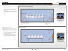
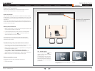
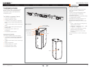
The Video Input Matrix
The video input matrix is found at the rear side of the codec and
illustrates the combinations in which the video inputs can be
connected.
About the matrix
Only one video input source from each row can be active at any time.
The numbers in the left column represents the Video Input Sources
1–5. The main connectors, which are used in basic setup, are marked
in orange color.
The Comp. 5 and S-Video (YC) 5 inputs uses the same physical
connectors and can not be connected at the same time.
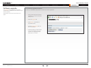
Configure the video inputs
You can configure the video input settings from the Administrator
Settings menu or by running API commands.
The default configurations are shown below:
What connectors are active is determined by the configuration of
the video input connector settings:
Video Input Source 1 Connector: HDMI•
Video Input Source 2 Connector: HDMI•
Video Input Source 3 Connector: DVI•
Video Input Source 4 Connector: HDMI•
Video Input Source 5 Connector: DVI•
The video name of the connector inputs should be set:
Video Input Source 1 Name: “Main Camera“•
Video Input Source 2 Name: “Secondary Camera“•
Video Input Source 3 Name: “PC“•
Video Input Source 4 Name: “DVD“•
Video Input Source 5 Name: “Document Camera“•
The video quality of the connector inputs should be set:
Video Input Source 1 Quality: Motion•
Video Input Source 2 Quality: Motion•
Video Input Source 3 Quality: Sharpness•
Video Input Source 4 Quality: Motion•
Video Input Source 5 Quality: Sharpness•
To determine the main video source and the default presentation
source for the system the following setting must be configured:
Video MainVideoSource: 1•
Video DefaultPresentationSource: 3•
* Comp 5 and YC 5 are not supported in version 1
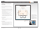
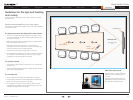
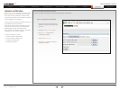
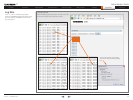
Administrator settings
Open the menu on screen to configure the video input sources
and which of the sources should be the main video source and
the default presentation source.
If the system is in standby mode, press any key on the remote
control to wake up the system.
Select: Settings > Administrator Settings > Advanced 1.
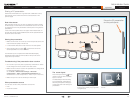
Configurations
From this point you can:2.
Search for the words “source” or “video” to see a list •
of the available Video Input Source [1–5] Connector
settings
- or,• you can navigate down in the list to Video > Input >
Source 1 > Connector
On the remote control, press the right arrow to edit the 3.
values
Select a value and press Save, or press Cancel to leave •
without saving.
Proceed and configure the:4.
Video Input Source Name, for the current input•
Video Input Source Quality, for the current input•
Video Main Video Source, for the system•
Video Default Presentation Source, for the system•
Line in
Rev.
Date
Prep.
Checked
Change
-
-
-
Telecom AS
-
-
-
-
-
-
-
-
-
-
-
-
-
-
-
-
-
-
Part weight:
Sheet size:
Scale:
Surface treatment
Specication:
Material
Tolerances
Unit:
European
projection
Sheet 1 of 1
All materials, nishes, and proccesses
must comply with the RoHS directives
Dimensions without paint or nish
Flame class requirement: -
Processes
Type:
Manufacturer:
Type number:
Thickness:
Color:
Surface:
Glossiness:
Flame class:
UL reference:
3D CAD model le 116805
rev. 00Z+ is master
Saturn C70 Unit
116805 rev.
3172g
A3
mm
1:5
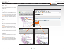
API commands
Open a telnet or ftp session to the codec to issue an API command to
configure the video input sources and which of the sources should be the
main video source and the default presentation source.
The following commands determines which connector to be active:
xconfiguration video input source 1 connector: hdmi•
xconfiguration video input source 2 connector: hdmi•
xconfiguration video input source 3 connector: dvi•
xconfiguration video input source 4 connector: hdmi•
xconfiguration video input source 5 connector: dvi•
Set the video quality and a name of the video inputs 1 to 5:
xconfiguration video input source 1 quality: motion•
xconfiguration video input source 1 name: “Main Camera“•
Configure the video inputs 2 to 5•
The main video source is the camera, connected to video input source 1:
xconfiguration video mainvideosource: 1•
The default presentation source is a PC, connected to video input source 3:
xconfiguration video defaultpresentationsource: 3•