


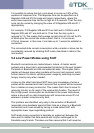
4.2 Mounting the blu
2i
Module onto the application
platform
There are many ways to properly install the Module in a host device. An
efficient approach is to mount the PCB to a frame, plate, rack or chassis.
Fasteners can be M1.8 or M2 screws plus suitable washers, circuit
board spacers, or customized screws, clamps, or brackets in 2.2mm
diameter holes. Note that care should be taken to ensure the head of the
fixing does not interfere with the circuit. Nylon fixings are recommended.
In addition, the board to board connection can also be utilized to achieve
better support.
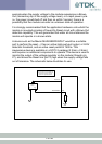
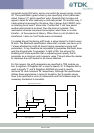
The antenna (Brown square component on top side of PCB) must not be
influenced by any other PCBs, components or by the housing of the host
device. The proximity of the antenna to large metallic objects can affect
the range and performance of the system. Designers should carefully
consider the location of the module and the type of enclosure material
that is used.
To prevent mechanical damage, be careful not to force, bend or twist the
module. Be sure it is positioned flat against the host device.
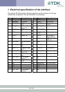
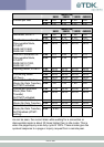
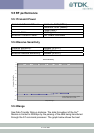
4.3 Board to Board Connector
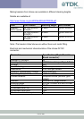
This section provides specifications for the 40 way board-to-board
connector which serves as physical interface to the host application. The
receptacle assembled on the blu
2i
Module is type Hirose DF12C.
Item Part number Stacking height HRS number
Receptacle
on Module
DF12C-40DS-
0.5V(81)
3.5mm - 5mm CL537-0007-7-
14 of 36