


blu
2i
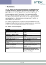
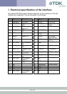
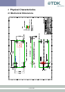
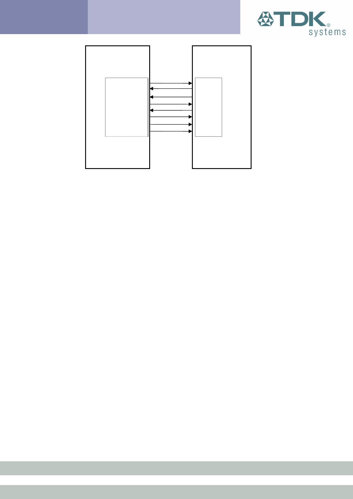
Module Application
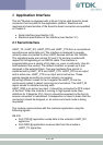
UART_TX /RXD
UART Interface
RS232 Interface
UART_RX /TXD
UART_CTS /RTS
UART_RTS /CTS
UART_DTS /DTR
UART_DTR /DSR
UART_DCD /DCD
UART RI
/
RING
Figure: UART interfaces
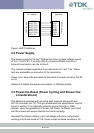
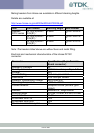
2.2 Power Supply
The power supply for the blu
2i
Module has to be a single voltage source
of Vcc= 3.6V to 6V. It must be able to provide sufficient current in a
transmit burst which can rise to 65mA.
The module includes regulators to provide local 3.3V and 1.8V. These
rails are accessible on connector J2 for monitoring.
Power (Vcc) should be provided via the board-to-board connector Pin 29
on J2.
Section 5.3 details the power consumption in different modes.
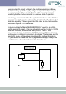
2.3 Power-On-Reset (Power Cycling and Brown Out
considerations)
The Module is provided with an active high reset pin (Hirose 40 way
DF12C connector pin 13). This pin whose electrical specification may be
found in section 3.3 is internally pulled to ground through a 10KΩ
resistor. Upon the application of power, the Power On Reset circuit built
into the module will ensure that the unit starts correctly.
However the module utilises a split rail design with some components
working at 3V3 and some at 1V8. Under certain extreme conditions, for
6 of 36