


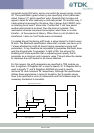
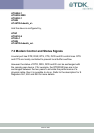
RS232 Modem Signals 6
Just as a telephony modem has control and status lines, the blu
2i
Module
also provides for 6 control and status lines as per the table below. The
direction column is as seen from the modules viewpoint.
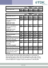
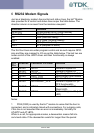
Direction Function
IN or OUT CI also known as RI (Ring Indicate)
IN or OUT DCD (Data Carrier Detect)
IN DSR (Data Set ready)
OUT DTR (Data Terminal Ready)
IN CTS (Clear to Send)
OUT RTS (Request to Send)
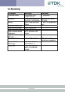
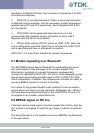
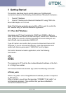
The first four lines are under program control and as such require GPIO
pins and they are mapped to I/O as per the table below. The last two are
under control of the UART driver and their functionality is always
enabled.
PIO
Pin
Direction Connector Pin Label Function
0 IN/OUT GPIO1 General Purpose I/O
1 IN/OUT GPIO2 General Purpose I/O
2 IN/OUT UART_RI Input/Output from module
3 IN/OUT UART_DCD Input/Output from module
4 IN UART_DSR Input to Module
5 IN/OUT GPIO3/UART_DTR General Purpose I/O (or
DTR functionality)
6 IN/OUT GPIO4 General Purpose I/O
(Right LED)
7 IN/OUT GPIO5 General Purpose I/O (Left
LED)
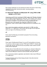
Notes:
1 PIO4 (DSR) is used by the blu
2i
module to sense that the host is
connected, and is intricately linked with connections. For outgoing calls,
if this line is not asserted then an error is immediately. Similarly for
AT+BTP and AT+BTG.
While in a call, for appropriate modes, a deassertion means fall into
command state. If the deassertion exists for longer than the period
24 of 36