


being transferred and when data is being transferred at the maximum
rate possible.
The operating mode can best be described by stating the AT commands
required to enter that mode. In addition, there are certain S Registers
which have a direct impact on power consumption, which are described
next.
The blu
2i
Module has 2 LEDs which can be configured to display
connection status. One led is used to display connection status, while
the other is used to either display ‘Ring Indicate’ status or follow the
state of the incoming DSR line on the UART interface. Tests have shown
that these LEDs can consume up to 5.3mA which is more than double
the current draw when in Idle mode. Therefore S Registers 533 and 534
can be used to completely disable these indications.
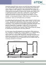
Finally S Registers 508 to 511, which specify the page and inquiry scan
intervals and windows, can be used to adjust the average current drain
when in discoverable and or connectable modes. Registers 508 and 509
specify the interval and window for page scans and registers 510 and
511 specify the interval and window for inquiry scans. Register pairs
508/509 and 510/511 describe duty cycles when the blu
2i
module goes
into scan modes. It is while scanning that the highest current draw
occurs. The average current draw is determined by simple arithmetic
using the values stored in the 508/509 and 510/511 register pairs.
The operating modes described above are entered using AT commands
as follows
Idle On power up, with S Register 512 = 1
Wait for Connection AT+BTG (100% page scan duty cycle)
Discoverable Only AT+BTQ (100% inquiry scan duty cycle)
Connecting ATD
Connected No Data
Connected Max data transfer
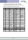
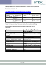
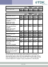
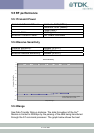
All current consumption values in the table below assume that the
connection status indication functionality of the LEDs has been disabled
by setting S Registers 533 and 534 to 0.
All current values are in milliamps (mA).
17 of 36