AT Commands
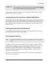
IMPORTANT!
Before you program the phone number and the system ID into the transceiver,
use the default pass code to unlock the transceiver: AT~NAMLCK=000000,
followed by AT~NAMVAL=nam, num, sid, nid <CR>
After you obtain CDMA service, use the LEDs on the OMEGA CDMA Modem to verify the
modem’s RSSI (see “LEDs” on page 17).
Attaching Mounting Feet (stand-alone OMEGA CDMA Modem)
The stand-alone OMEGA CDMA Modem comes with a Mounting Feet Kit that allows flexible
mounting options for the OMEGA CDMA Modem. To use the mounting feet, align the hole on
each mounting foot with the mounting hole on the OMEGA CDMA Modem and secure with a
screw. Then use the hole on the other end of the mounting foot to secure the OMEGA to the
appropriate surface.
Installing the Optional 8-Port RS-232 Module
If you purchased the optional 8-port RS-232 module, refer to Appendix B for instructions on
installing the module in the OMEGA CDMA Modem.
Power Supply Connections
Note:
If the Marwell socket adapter option has been purchased from Telenetics, skip this
section.
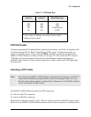
For OMEGA CDMA Modems equipped with an AC power connector, connect the OMEGA
CDMA Modem to a single phase AC source in the range of 90 VAC to 277 VAC, at 50 or 60
Hz. Use a UL-listed and approved power cord, with a rating of 10 amps or above and a
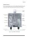
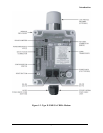
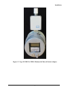
maximum wire size of 16 AWG. Figure 1-1 on page 7 and Figure 1-2 on page 8 show the
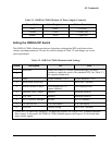
location of the OMEGA CDMA Modem power connector. Table 2-1 lists the AC power
connector reference information.
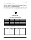
For OMEGA CDMA Modems equipped with the DC low-voltage power supply option, a 3.3
VDC power source is necessary.
Page 12


