


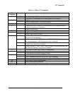
AT Commands
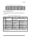
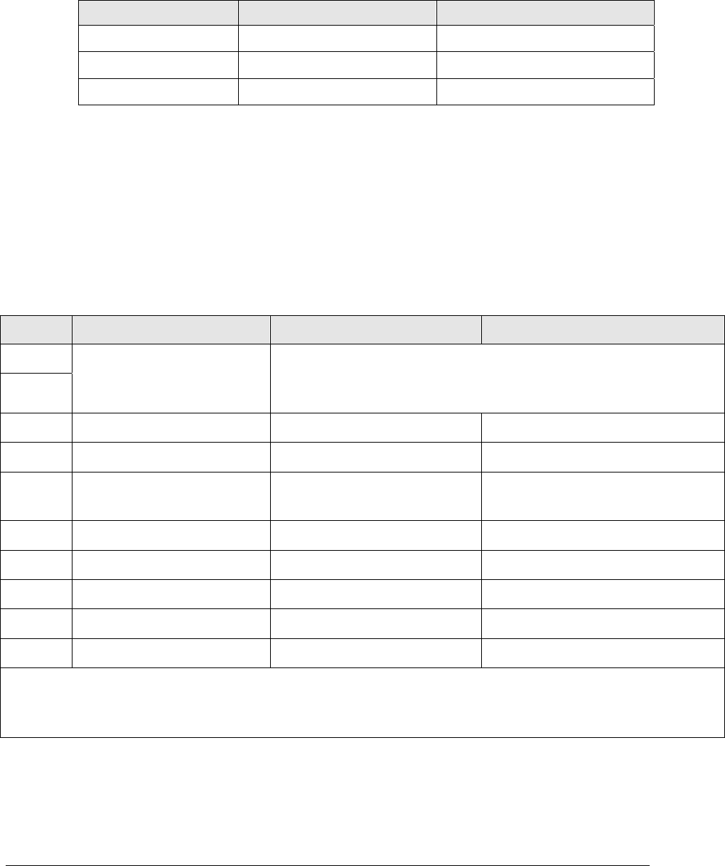
Table 2-1. OMEGA CDMA Modem AC Power Supply Connector
Power Cable Color Designation Modem Terminal
Live Black 1 (left pin)
Ground Green 2 (center pin)
Neutral White 3 (right pin)
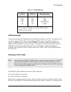
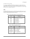
Setting the OMEGA DIP Switch
The OMEGA CDMA Modem provides an 8-position configuration DIP switch that selects
various operating parameters. Review the switch settings in Table 2-2 and change any to suit
your requirements.
Table 2-2. OMEGA CDMA Modem Switch Settings
Switch Description ON OFF
1
2
Baud Rate Selects the OMEGA CDMA Modem baud rate. Set these
switches to match the speed of the attached DTE. See Table 2-3
for supported baud rates.
3 Parity Async character: 8-E-1 Async character: 8-N-1
4 Sleep Mode (Reserved) Set to OFF (default)
5 Interface Status or RSSI LEDs display RS-232
signals (default)
LEDs display RSSI
6 Hardware Flow Control* Enabled Disabled (default)
7 DTR Dial Enabled Disabled (default)
8 RS-232/RS-485 Interface RS-485 RS-232 (default)
9 2/4 wire RS-485 2-W Half-duplex 4-W Full-duplex
10 Reserved Factory testing Set to OFF (default)
* If your RTU or meter only supports TXD and RXD signals, set switch 6 OFF to disable hardware
flow control. In this mode, the OMEGA CDMA Modem ignores the Request-To-Send and other
input control signals.
Page 13