


2-2
10 July 1998
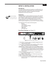
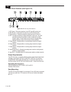
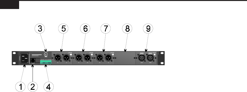
Rear Panel Features (see Figure 2-2)
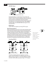
Figure 2-2
ISP-100 rear panel features.
1. AC Power—Connects to mains via an IEC type AC power cord.
2. RS-232 Port—Links the PC to the unit via a RJ-45 connector.
3. External Sync—Precision frequency reference input to the unit.
4. GPI—Provides a General Purpose Interface for the user. The user
provides inputs to the system via dry or electronic contact
closure inputs. These inputs can be used to change system
settings directly and/or scroll through various settings.
5. Output Slot 5—Accepts either an analog output module or digital
module.
6. Output Slot 4—Accepts either an analog output module or digital
module.
7. Output Slot 3—Accepts either an analog output module or digital
module.
8. Input/Output Slot 2—Accepts an analog input module, analog output
module, or digital module.
9. Input Slot 1—Accepts either an analog input module or digital module.
Power Requirements
The ISP-100 uses a universal switching power supply that accepts input
voltages in the range of 90 VAC to 264 VAC, 50/60 Hz. All countries
using 220/240 VAC except Australia use a ½ amp slow-blow fuse. All
countries using 100/120 VAC and Australia use a 1 amp slow-blow fuse.
Operating Environment
Internal temperature: 50°F to 95°F (10°C to 35°C)
Humidity: 20% to 80%
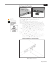
Rack Mounting
The ISP-100 may be installed in a standard 19-inch (483-mm) equipment
rack with one rack unit (1.75 inches or 44.5 mm) of vertical rack space
per unit.