


7-17
Using VUE-IT
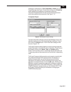
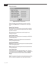
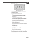
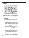
Device Status Panel
Figure 7-23
Device status panel.
Clicking on the entry next to the star icon (see Figure 7-9) and then
clicking on the Design button in the Project Manager opens the Device
Status Panel. See Figure 7-23.
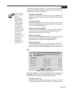
The device status panel has five simulated LEDs:
Clock Sync (red)
The main board cannot lock to specified location or frequency.
Digital Data (red)
1. Data validity error. Card position dependent.
2. A non-48 kHz Sample Rate is being used, and no Sample Rate
Converter is selected. Card position dependent.
3. Non-Audio Input Stream. Card position dependent.
4. Slot Cannot be chosen as master and have sample rate converter
present. Card position dependent.
5. An input slot must have an AES card to be master. Card position
dependent.
Low Battery (yellow)
Please check battery.
Input Clip (red)
Input audio has clipped before the DSPs.
Process Clip (red)
Which slot and channel caused the clip.
The specifics of an error condition can be found by clicking on the ?
button. You are also able to clear the error indication. If the error condition
still exists or reoccurs, the error LED will turn on again.