


8-19
Processing Components - Crossover
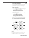
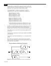
Four-way Linkwitz-Riley Crossovers
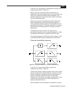
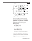
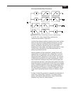
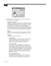
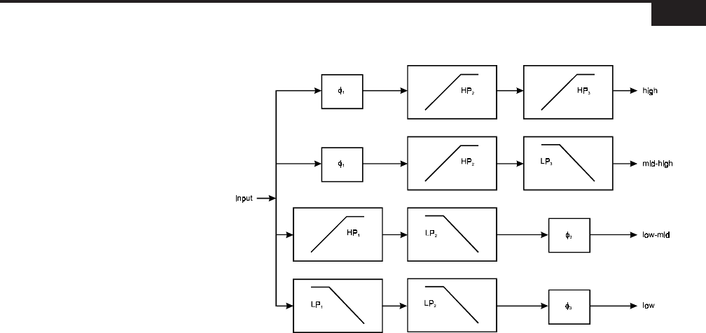
Figure 8-10
Four-way Linkwitz-Riley crossover implementation.
In the ISP-100, 4-way Linkwitz-Riley crossovers are
implemented as shown in Figure 8-10.
Linkwitz-Riley designs constitute a special, even-order in-phase
class of 2-way sum-to-allpass response crossovers, and they
must be configured in accordance with very strict phase and
polarity requirements. Because the basic Linkwitz-Riley
crossover is a 2-way design, extra steps must be taken in 4-way
Linkwitz-Riley crossovers to ensure that these phase and
polarity requirements are met.
Note the presence of the unexpected θ
1
allpass filter and HP
2
highpass filter in the high band, the θ
1
allpass filter in the mid-
high band, the θ
3
allpass filter in the low-mid band, and the LP
2
lowpass filter and θ
3
allpass filter in the low band. The inclusion
of these filters is mandatory for proper implementation of the 4-
way Linkwitz-Riley crossover; they ensure that the phase shift
and magnitude response in each band match those of the other
bands to maintain the fundamental Linkwitz-Riley sum-to-allpass
quality. A detailed explanation of the use of compensation filters
such as these may be found in “Active Realization of Multiway
All-Pass Crossover Systems” by Joseph A. D’Appolito;
Journal
of the Audio Engineering Society
, Volume 35, Number 4, April
1987.
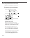
A 4-way Linkwitz-Riley crossover is essentially a combination of
three 2-way Linkwitz-Riley crossovers. This means that the
polarity requirements associated with a 2-way Linkwitz-Riley
crossover carry over to a 4-way crossover.