


2-5
Setup & Installation
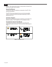
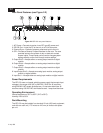
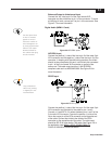
Balanced Output to Unbalanced Input
Connect the “hot” wire to pin 2 of the 3-pin female XLR
connector and the shield wire to pin 1 of the connector. To avoid
a 6 dB drop in level, connect pin 3 to pin 1 of the connector. See
Figure 2-7 for more information.
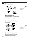
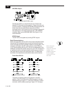
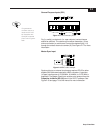
Digital Audio (MDM-1 Cards)
Figure 2-8
AES/EBU inputs.
AES/EBU Input
Connect the positive (+) side of the line to pin 2 of the male 3-pin
XLR connector and the negative (-) side of the line to pin 3 of the
connector. In keeping with standard wiring practices, the shield
should not be connected at this end; it should only be connected
to pin 1 of the 3-pin female XLR connector or ground of the
source end. The cable used should be 110Ω AES/EBU
compliant cable such as MOGAMI 3080. See Figure 2-8 for
more information.
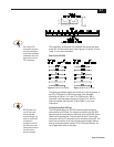
SPDIF Input
Figure 2-9
SPDIF inputs.
Connect the positive (+) side of the line to pin 2 of the male 3-pin
XLR connector and the shield of the cable to pins 1 and 3.
Connect a ¼ watt 237Ω 1% resistor between pins 1 and 2 of the
3-pin male XLR connector. Connect the positive (+) side of the
line to the center pin of the RCA connector on the opposite end
of the cable. Connect the shield to the shield of the RCA
connector on the opposite end of the cable. The cable used
should be RG-59 or other similar 75Ω cable. See Figure 2-9 or
the application note MDM-1 SPDIF COMPATABILITY
P/N 42-02-053086 for more information.
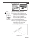
Use the white block
on the I/O module
panels to write a
reference number or
other designator on
by using a permanent
marker. Then make
identical labels for
the cables that plug
into the module.
Long unbalanced
cable runs (analog
or digital) are not
recommended.