


www.ti.com
2.2PLL1Control
PLLDIV1(/1)
PLLDIV3(/6)
PLLDIV2(/3)
SYSCLK1
(CLKDIV1Domain)
SYSCLK3
(CLKDIV6Domain)
SYSCLK2
(CLKDIV3Domain)
1
0
PLLM
PLL
0
1
CLKMODE
CLKIN
OSCIN
PLLEN
AUXCLK
(CLKINDomain)
OSCDIV1
OBSCLK
(CLKOUT0Pin)
PLLOUT
PLLController
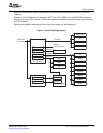
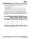
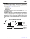
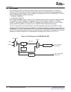
PLL1suppliestheprimaryC642xDSPsystemclock.SoftwarecontrolsthePLL1operationthroughthe
systemPLLcontroller1(PLLC1)registers.TheregistersusedinPLLC1arelistedinSection2.4.Figure2
showsthecustomizationofPLL1intheC642xDSP.Thedomainclocksaredistributedtothecoreclock
domains(discussedinSection1.2.1)andtherestofthedeviceasfollows:
•SYSCLK1:CLKDIV1Domain
•SYSCLK2:CLKDIV3Domain
•SYSCLK3:CLKDIV6Domain
•AUXCLK:CLKINDomain
•OBSCLK:CLKOUT0pin
ThePLL1multiplieriscontrolledbythePLLMbitofthePLLmultipliercontrolregister(PLLM).ThePLL1
outputclockmaybedivided-downforslowerdeviceoperationusingthePLLC1SYSCLKdividers
PLLDIV1,PLLDIV2,andPLLDIV3.
YouareresponsibletoadheretothePLLC1frequencyrangesandmultiplier/dividerratiosspecifiedinthe
datamanual.SeealsoSection1.2.1andSection1.2.2.
Atpower-up,PLL1ispowered-downanddisabled,andmustbepowered-upbysoftwarethroughthePLL1
PLLPWRDNbitinthePLLcontrolregister(PLLCTL).Bydefault,thesystemoperatesinbypassmodeand
thesystemclockisprovideddirectlyfromtheinputreferenceclock(MXI/CLKINpin).OncethePLLis
powered-upandlocked,softwarecanswitchthedevicetoPLLmodeoperationbysettingthePLLENbitin
PLLCTLto1.Ifthebootmodeofthedeviceissettofastboot(FASTBOOT=1),thebootloadercodein
theBootROMwillfollowthepreviousprocesstopower-upandlockthePLL,andswitchthedevicetoPLL
modetospeedupthebootprocess.Therefore,comingoutofafastboot,thedeviceisoperatinginPLL
mode.
Figure2.PLL1StructureintheTMS320C642xDSP
12Phase-LockedLoopController(PLLC)SPRUES0B–December2007
SubmitDocumentationFeedback