


Address or I/O
Read/Write
Chip select
Data strobe
A
Data/address
Interrupt
Ready
HCNTL[1:0]
HR/W
HCS
HDS1
HDS2
HD[31:0]
HINT
HRDY
HPIHost
Logic high HAS
No connect HHWIL
Logic high
2
32
DSP
Read/Write
Chip select
Data strobe
A
Data/address
Interrupt
Ready
HCNTL[1:0]
HR/W
HCS
HDS1
HDS2
HD[15:0]
HINT
HRDY
HPI
DSP
Host
Address latch enable HAS
HHWIL
Logic
high
HD[31:16]
No
connect
2
16
16
www.ti.com
HPI Operation
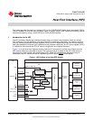
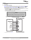
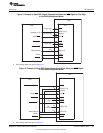
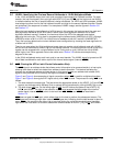
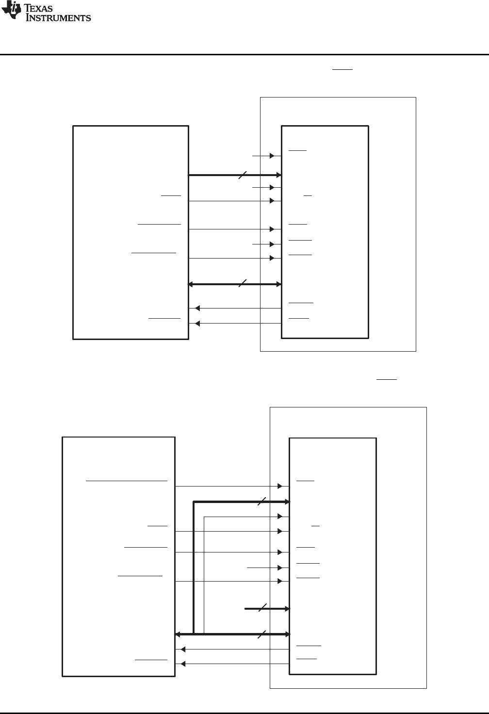
Figure 3. Example of Host-DSP Signal Connections When the HAS Signal is Tied High
in the 32-Bit Multiplexed Mode
A Data strobing options are given in Section 3.3.
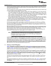
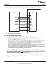
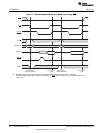
Figure 4. Example of Host-DSP Signal Connections When Using the HAS Signal
in the 16-Bit Multiplexed Mode
A Data strobing options are given in Section 3.3.
13
SPRUGK7A–March 2009–Revised July 2010 Host Port Interface (HPI)
Copyright © 2009–2010, Texas Instruments Incorporated