


www.ti.com
List of Figures
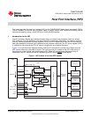
1 HPI Position in the Host-DSP System ................................................................................... 7
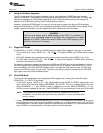
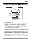
2 Example of Host-DSP Signal Connections When Using the HAS Signal in the 32-Bit Multiplexed Mode .... 12
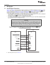
3 Example of Host-DSP Signal Connections When the HAS Signal is Tied High in the 32-Bit Multiplexed
Mode ........................................................................................................................ 13
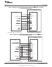
4 Example of Host-DSP Signal Connections When Using the HAS Signal in the 16-Bit Multiplexed Mode .... 13
5 Example of Host-DSP Signal Connections When the HAS Signal is Tied High in the 16-Bit Multiplexed
Mode ........................................................................................................................ 14
6 HPI Strobe and Select Logic............................................................................................. 15
7 16-Bit Multiplexed Mode Host Read Cycle Using HAS .............................................................. 18
8 16-Bit Multiplexed Mode Host Write Cycle Using HAS .............................................................. 19
9 16-Bit Multiplexed Mode Host Read Cycle With HAS Tied High.................................................... 20
10 16-Bit Multiplexed Mode Host Write Cycle With HAS Tied High .................................................... 21
11 16-Bit Multiplexed Mode Single-Halfword HPIC Cycle with HAS Tied High ....................................... 22
12 HRDY Behavior During an HPIC or HPIA Read Cycle in the 16-Bit Multiplexed Mode.......................... 23
13 HRDY Behavior During a Data Read Operation in the 16-Bit Multiplexed Mode (Case 1: HPIA Write
Cycle Followed by Nonautoincrement HPID Read Cycle) ........................................................... 23
14 HRDY Behavior During a Data Read Operation in the 16-Bit Multiplexed Mode (Case 2: HPIA Write
Cycle Followed by Autoincrement HPID Read Cycles) .............................................................. 23
15 HRDY Behavior During an HPIC Write Cycle in the 16-Bit Multiplexed Mode .................................... 24
16 HRDY Behavior During a Data Write Operation in the 16-Bit Multiplexed Mode (Case 1: No
Autoincrementing) ......................................................................................................... 24
17 HRDY Behavior During a Data Write Operation in the 16-Bit Multiplexed Mode(Case 2: Autoincrementing
Selected, FIFO Empty Before Write).................................................................................... 24
18 HRDY Behavior During a Data Write Operation in the 16-Bit Multiplexed Mode(Case 3: Autoincrementing
Selected, FIFO Not Empty Before Write)............................................................................... 25
19 HRDY Behavior During an HPIC or HPIA Read Cycle in the 32-Bit Multiplexed Mode.......................... 25
20 HRDY Behavior During a Data Read Operation in the 16-Bit Multiplexed Mode (Case 1: HPIA Write
Cycle Followed by Nonautoincrement HPID Read Cycle) ........................................................... 26
21 HRDY Behavior During a Data Read Operation in the 32-Bit Multiplexed Mode (Case 2: HPIA Write
Cycle Followed by Autoincrement HPID Read Cycles) .............................................................. 26
22 HRDY Behavior During an HPIC Write Cycle in the 32-Bit Multiplexed Mode .................................... 27
23 HRDY Behavior During a Data Write Operation in the 32-Bit Multiplexed Mode (Case 1: No
Autoincrementing) ......................................................................................................... 27
24 HRDY Behavior During a Data Write Operation in the 32-Bit Multiplexed Mode (Case 2:
Autoincrementing Selected, FIFO Empty Before Write).............................................................. 28
25 HRDY Behavior During a Data Write Operation in the 32-Bit Multiplexed Mode (Case 3:
Autoincrementing Selected, FIFO Not Empty Before Write)......................................................... 28
26 Host-to-CPU Interrupt State Diagram................................................................................... 30
27 CPU-to-Host Interrupt State Diagram................................................................................... 31
28 FIFOs in the HPI........................................................................................................... 32
29 Power and Emulation Management Register (PWREMU_MGMT) ................................................. 37
30 Host Access Permissions ................................................................................................ 38
31 CPU Access Permissions ................................................................................................ 38
32 Format of an Address Register (HPIAW or HPIAR) - Host Access Permissions ................................. 40
33 Format of an Address Register (HPIAW or HPIAR) - CPU Access Permissions ................................. 40
34 Data Register (HPID) (Host access permissions, CPU cannot access HPID) .................................... 41
4
List of Figures SPRUGK7A–March 2009–Revised July 2010
Copyright © 2009–2010, Texas Instruments Incorporated