


ListofFigures
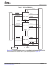
1-1MultipleePWMModules...................................................................................................15
1-2SubmodulesandSignalConnectionsforanePWMModule.........................................................16
1-3ePWMSubmodulesandCriticalInternalSignalInterconnects......................................................17
2-1Time-BaseSubmoduleBlockDiagram..................................................................................23
2-2Time-BaseSubmoduleSignalsandRegisters.........................................................................24
2-3Time-BaseFrequencyandPeriod.......................................................................................26
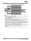
2-4Time-BaseCounterSynchronizationScheme1.......................................................................27
2-5Time-BaseCounterSynchronizationScheme2.......................................................................28
2-6Time-BaseCounterSynchronizationScheme3.......................................................................29
2-7Time-BaseUp-CountModeWaveforms................................................................................30
2-8Time-BaseDown-CountModeWaveforms.............................................................................31
2-9Time-BaseUp-Down-CountWaveforms,TBCTL[PHSDIR=0]CountDownOnSynchronizationEvent......31
2-10Time-BaseUp-DownCountWaveforms,TBCTL[PHSDIR=1]CountUpOnSynchronizationEvent.........32
2-11Counter-CompareSubmodule............................................................................................32
2-12DetailedViewoftheCounter-CompareSubmodule...................................................................33
2-13Counter-CompareEventWaveformsinUp-CountMode.............................................................35
2-14Counter-CompareEventsinDown-CountMode.......................................................................35
2-15Counter-CompareEventsInUp-Down-CountMode,TBCTL[PHSDIR=0]CountDownOn
SynchronizationEvent....................................................................................................36
2-16Counter-CompareEventsInUp-Down-CountMode,TBCTL[PHSDIR=1]CountUpOnSynchronization
Event........................................................................................................................36
2-17Action-QualifierSubmodule...............................................................................................37
2-18Action-QualifierSubmoduleInputsandOutputs.......................................................................38
2-19PossibleAction-QualifierActionsforEPWMxAandEPWMxBOutputs............................................39
2-20Up-Down-CountModeSymmetricalWaveform........................................................................42
2-21Up,SingleEdgeAsymmetricWaveform,WithIndependentModulationonEPWMxAand
EPWMxB—ActiveHigh....................................................................................................43
2-22Up,SingleEdgeAsymmetricWaveformWithIndependentModulationonEPWMxAand
EPWMxB—ActiveLow....................................................................................................44
2-23Up-Count,PulsePlacementAsymmetricWaveformWithIndependentModulationonEPWMxA..............45
2-24Up-Down-Count,DualEdgeSymmetricWaveform,WithIndependentModulationonEPWMxAand
EPWMxB—ActiveLow...................................................................................................47
2-25Up-Down-Count,DualEdgeSymmetricWaveform,WithIndependentModulationonEPWMxAand
EPWMxB—Complementary.............................................................................................48
2-26Up-Down-Count,DualEdgeAsymmetricWaveform,WithIndependentModulationonEPWMxA—Active
Low...........................................................................................................................49
2-27Dead_BandSubmodule...................................................................................................50
2-28ConfigurationOptionsfortheDead-BandSubmodule................................................................51
2-29Dead-BandWaveformsforTypicalCases(0%<Duty<100%).....................................................53
2-30PWM-ChopperSubmodule...............................................................................................55
2-31PWM-ChopperSubmoduleOperationalDetails........................................................................56
2-32SimplePWM-ChopperSubmoduleWaveformsShowingChoppingActionOnly..................................56
2-33PWM-ChopperSubmoduleWaveformsShowingtheFirstPulseandSubsequentSustainingPulses.........57
2-34PWM-ChopperSubmoduleWaveformsShowingthePulseWidth(DutyCycle)ControlofSustaining
Pulses........................................................................................................................58
2-35Trip-ZoneSubmodule......................................................................................................59
2-36Trip-ZoneSubmoduleModeControlLogic.............................................................................62
2-37Trip-ZoneSubmoduleInterruptLogic....................................................................................63
2-38Event-TriggerSubmodule.................................................................................................63
2-39Event-TriggerSubmoduleInter-ConnectivityofADCStartofConversionandInterruptSignals................64
2-40Event-TriggerSubmoduleShowingEventInputsandPrescaledOutputs..........................................65
2-41Event-TriggerInterruptGenerator........................................................................................66
2-42Event-TriggerSOCAPulseGenerator..................................................................................67
SPRU791D–November2004–RevisedOctober2007ListofFigures5
SubmitDocumentationFeedback