


SLUU195 − June 2004
11
TPS40090 Multi-Phase Buck Converter and TPS2834 Drivers Steps-Down from 12-V to 1.5-V at 100 A
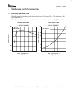
3. Transient consideration. An additional consideration in the selection of the output inductor
and capacitance value can be derived from examining the transient voltage overshoot
which can be initiated with a load step from full load to no load. By equating the inductive
energy with the capacitive energy the equation (10) can be derived.
C
OUT
+
L I
2
V
2
+
L
EQ
ǒ
ǒ
I
OH
Ǔ
2
*
ǒ
I
OL
Ǔ
2
Ǔ
ǒ
V
OUT2
Ǔ
2
*
ǒ
V
OUT1
Ǔ
2
+
0.6mH
4
(
100 A
)
2
ǒ
(
1.75 V
)
2
*
(
1.5 V
)
2
Ǔ
+ 1846 mF
where
• I
OH
is full load
• I
OL
is no load
• V
OUT2
is the the allowed transient voltage rise
• V
OUT1
is the initial voltage
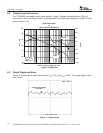
In this 100-A design the capacitance required for limiting the transient is significantly larger than
the capacitance required to keep the ripple acceptably low. Eight 220-µF POSCAP capacitors
are in parallel with four 22-µF ceramic capacitors. The ESR of each POSCAP is 15mΩ.
4.5 MOSFET Selection
There are different requirements for switching FET(s) and rectifier FET(s) in the high-ratio step
down application. The duty cycle is around 12%. So the rectifier FET(s) is on for most of the
cycle. The conduction loss is dominant. Low-R
DS(on)
FET(s) are preferred. Also due to the dV/dt
turn on of the rectifier FET(s) and cross conduction, choose a rectifier FET with Qgs > Qgd.
When the switch node is falling, the Qgd can pull the gate of the lower FET below GND, which
upsets the driver. Two Si7880DP from Siliconix are in parallel for the rectifier FET. The R
DS(on)
of
this FET is 3 mΩ and Qgs=18nC, and Qgd=10.5nC.
The switching FET switches at high voltage and high current, the switching loss is dominant.
One single Si7860DP is selected for its low total gate charge.
Both types of FET(s) are offered in the Powerpak SO−8 package.
The PCB is layed out for two FETs in parallel, for both switching FET(s) and rectifier FET(s), to
give the feasibility to modify the board for different applications.
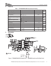
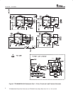
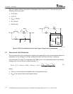
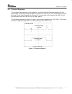
4.6 Current Sensing
TPS40090 supports both resistor current sensing and DCR current sensing approach. DCRs of
the output inductors are used in this design as the current sensing components. The DCR
current sensing circuit is shown in Figure 5. The idea is to parallel a R-C network to the inductor.
If the two time constants are same (L/DCR=R × C), then V
C
=V
DCR
. Extra circuit, shown in (b), is
used to compensate the positive temperature coefficient of copper specific resistance, which is
0.385%/°C. See detail explanation in the datasheet.
(10)